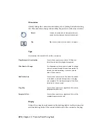
When the connector is built, the plug side wire connection attrib-
ute is moved from the insertion point on the divider line to the
outside line representing the plug. The associated terminal pin
attribute (TERM01_) travels half the distance as the wire connec-
tion attribute placing itself in the middle between the dimension
on the divider line.
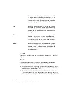
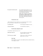
Specifies the distance from the top or breaking point of the con-
nector to the first or next wire connection point. This determines
Top
where the top line is drawn relative to the first master symbol
insertion point. The distance is used for the entire connector or
breaking the connector.
Specifies the distance from the bottom or breaking point of the
connector to the last or previous wire connection point. This de-
Bottom
termines where the bottom line is drawn relative to the last
master symbol insertion point. The distance is used for the entire
connector or breaking the connector.
Specifies the radial dimension of the rounded portion of the plug
representation. If left blank, a radius is not created on the plug
Radius
connector. If you enter a value that exceeds the overall plug side
distance, the radius value is erased and the radius is not created
on the plug connector.
Pick File
Displays the Connector List File Selection dialog box to select a new file for
import.
Wire It
Reviews connectors placed on the active drawing and runs the wiring
commands to make connections between the connectors.
■
When both ends of the wire connections are found on the active drawing,
the wires are generated between the two points and wire numbering is
added based on current configurations.
■
When only one end of the wire connection is found on the active drawing,
text is placed next to the connector in the X?WIREnn wire annotation
attribute on the connector symbol. This text is overwritten when the second
Overview of the spreadsheet import file structure | 683
Summary of Contents for 22505-051400-9000 - AutoCAD Electrical 2008
Page 1: ...AutoCAD Electrical 2008 User s Guide February 20 2007 ...
Page 4: ...1 2 3 4 5 6 7 8 9 10 ...
Page 106: ...94 ...
Page 228: ...216 ...
Page 242: ...HP W TERM_ VDC SPECIAL SPACINGFACTOR 0 5 HP WA D TERM_ 02 230 Chapter 5 PLC ...
Page 294: ...282 ...
Page 564: ...552 ...
Page 698: ...686 ...
Page 740: ...728 ...
Page 814: ...802 ...
Page 1032: ...1020 ...
Page 1134: ...1122 ...
Page 1168: ...1156 ...
Page 1177: ...Insert P ID Component Overview of pneumatic tools 1165 ...
Page 1198: ...1186 ...
Page 1269: ...AutoCAD Electrical Command In this chapter AutoCAD Electrical Commands 20 1257 ...
Page 1304: ...Z zip utility 82 1292 Index ...


