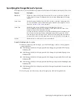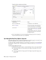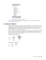
Design Rules tab for an electrical system definition
3
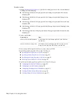
Configure the design rules:
then…
If you want to…
for Abbreviation, enter an abbreviation.
specify a system abbreviation
for System Group, select or enter a group name.
New names are added to the list of existing names.
specify a
for Layer Key, select a layer key. The list of available
layer keys depends on the
for the drawing.
To create a layer key override, click [...] beside the
appropriate Layer Field, select an override value in
the dialog, and click OK.
select a layer key
4
If the system definition is for electrical or plumbing, for System Type, select a system type.
The list of available system types is not customizable.
Specifying the Rise/Drop Style of a System
Rise symbols and drop symbols represent the elevation direction of vertical segments in your layout for any
predefined orthographic view (top, bottom, left, right, front, or back).
Rise/drop styles define the graphical appearance of rises and drops in your layout. You can assign different
rise/drop styles to different systems. For information about creating a rise/drop style, see
on page 612.
To specify the rise/drop style of a system
1
Within the domain-specific workspace, open the Style Manager and access the system definitions:
■
Click Manage tab
➤
Style & Display panel
➤
Style Manager drop-down
➤
HVAC System
Definitions
.
■
Click Manage tab
➤
Style & Display panel
➤
Style Manager drop-down
➤
Piping System
Definitions
.
98 | Chapter 4 Drawing Essentials
Summary of Contents for 235B1-05A761-1301 - AutoCAD MEP 2010
Page 1: ...AutoCAD MEP 2010 User s Guide March 2009 ...
Page 22: ...4 ...
Page 86: ...68 ...
Page 146: ...128 ...
Page 180: ...162 ...
Page 242: ...Modifying the elevation of a duct 224 Chapter 6 Drawing HVAC Systems ...
Page 264: ...246 ...
Page 480: ...462 ...
Page 534: ...516 ...
Page 616: ...598 ...
Page 658: ...640 ...
Page 788: ...770 ...
Page 802: ...784 ...
Page 820: ...802 ...
Page 878: ...860 ...

