If you change a space from associative to non-associative or vice versa, existing openings are maintained in
most cases. When you change a 3D free form space to a 3D extruded space, openings that do not intersect
with the base profile of the extruded space are lost.
Modeling Surface Types on Spaces
Space surfaces can be configured for surface type. For example, a wall can be interior or exterior, and a floor
can be interior, slab, or underground. However, you do not need to specify surface types in order to use the
gbXML export tool. The tool automatically figures out the correct surface type when the gbXML file is
created. For example, surfaces that have no adjacent spaces are considered exterior, and wall surfaces below
grade level (z = 0) are considered underground. You can specify surface types in the
Adding Engineering Data to Spaces
For load calculation purposes, you must add SpaceEngineeringObjects, ThermalProperties, and
ZoneEngineeringObjects styles property sets to all spaces that you want to analyze. From the Style Manager,
copy property set definitions from the gbXML Property Set Definitions drawing into your current drawing.
Once you have assigned these property set definitions to the spaces and zones in your drawing, you can edit
the engineering data to model the appropriate environmental conditions. You are then ready export this
data in gbXML format for use in various analysis software programs.
1
Click Manage tab
➤
Style & Display panel
➤
Style Manager
.
2
Click File
➤
Open Drawing.
3
In the Open Drawing dialog, navigate to \ProgramData\Autodesk\MEP
2010\enu\Styles\Imperial.
4
Select the gbXML Property Set Definitions drawing and click Open.
5
Expand the gbXML Property Set Definitions Documentation Objects folder.
6
Select Property Set Definitions.
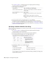
The SpaceEngineeringObjects, ThermalProperties, and ZoneEngineeringObjects styles comprise
this property set.
7
Copy the Property Set Definitions to your current drawing, and then click OK.
The engineering data styles are ready to be applied the spaces and zones in your drawing.
8
Select the spaces to which you want to add the property set data, and click Home tab
➤
Build
panel
➤
Tools drop-down
➤
Properties
.
9
On the Properties palette, click the Extended Data tab, and then click
(Add Property Sets).
10
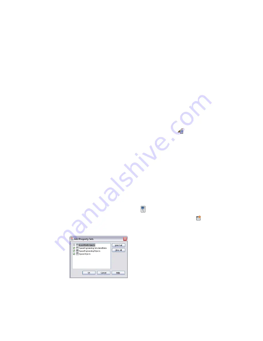
In the Add Property Sets dialog, select SpaceEngineeringCalculatedData, SpaceEngineeringObjects,
and SpaceObjects, and then click OK.
Adding Engineering Data to Spaces | 187
Summary of Contents for 235B1-05A761-1301 - AutoCAD MEP 2010
Page 1: ...AutoCAD MEP 2010 User s Guide March 2009 ...
Page 22: ...4 ...
Page 86: ...68 ...
Page 146: ...128 ...
Page 180: ...162 ...
Page 242: ...Modifying the elevation of a duct 224 Chapter 6 Drawing HVAC Systems ...
Page 264: ...246 ...
Page 480: ...462 ...
Page 534: ...516 ...
Page 616: ...598 ...
Page 658: ...640 ...
Page 788: ...770 ...
Page 802: ...784 ...
Page 820: ...802 ...
Page 878: ...860 ...

