5
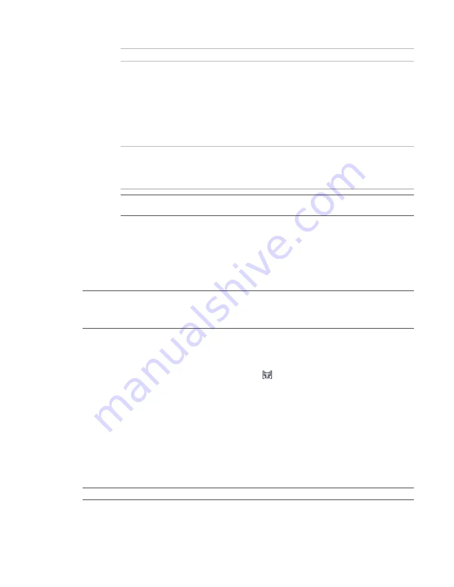
To specify the upper and lower limits for a size range, do the following:
then ...
If you want to specify ...
select a size for Size Upper Limit. You can select from
the list of nominal sizes that are common to all of the
selected parts in the size range.
If a subsequent size range exists, its lower limit is
changed based on the upper limit you selected for
the current size range.
the upper limit
If you need to select a larger size than is allowed in
the list of choices, select different parts for the size
range.
change the value for Size Upper Limit for the preced-
ing size range.
The lower limit of Size Range 1 is always defined by
the selected parts in the range.
the lower limit
TIP
You can switch the order of 2 size ranges by changing the upper limit of one range so that it is
larger or smaller than the other.
6
Enter a description for the size range, if desired.
7
Add a range to designate a new size range.
The new size range is appended to the list of ranges. Its lower limit is the next catalog size up
from the upper limit for the preceding size range, and its upper size limit is the largest catalog
size.
8
To delete a range, select the name of the size range, and click Remove Size Range.
NOTE
It is possible to create and save an invalid size range. For example, specifying an upper limit that is already
in use by another size range could invalidate the size range. If a size range is invalid, *Invalid Size Range* is specified
for Size Upper Limit in the routing preference definition, and the sizes in that range are unavailable nominal sizes
on the Properties palette.
Deleting a Routing Preference
1
In the
, click Manage tab
➤
Style & Display panel
➤
Style Manager
drop-down
➤
Routing Preference Definitions
.
2
In the left pane of Style Manager, right-click the routing preference you want to delete, click
Purge, and then click OK.
Configuring System Definitions
Pipe system definitions specify display properties, such as pipe display by size, layer key settings, and rise/drop
display style.
Creating a System Definition
TIP
The default templates contain several system definitions that you can copy or modify.
Configuring System Definitions | 281
Summary of Contents for 235B1-05A761-1301 - AutoCAD MEP 2010
Page 1: ...AutoCAD MEP 2010 User s Guide March 2009 ...
Page 22: ...4 ...
Page 86: ...68 ...
Page 146: ...128 ...
Page 180: ...162 ...
Page 242: ...Modifying the elevation of a duct 224 Chapter 6 Drawing HVAC Systems ...
Page 264: ...246 ...
Page 480: ...462 ...
Page 534: ...516 ...
Page 616: ...598 ...
Page 658: ...640 ...
Page 788: ...770 ...
Page 802: ...784 ...
Page 820: ...802 ...
Page 878: ...860 ...


