then…
If you want to…
Under Insertion Point, specify the new X, Y, and Z coordinates.
enter coordinates to specify a new loc-
ation
Under Normal, specify 1 for the normal axis, and specify 0 for the
other 2 axes.
change the normal axis, and reorient
the part along the new normal
Modifying Connected Objects Along a Pipe Run
When you change a dimension associated with a pipe or fitting that is connected to other objects, you can
modify the routing properties for a pipe or fitting going in the same direction along the pipe run.
1
Select a pipe.
2
Click Pipe tab
➤
Modify panel
➤
Modify Run
.
3
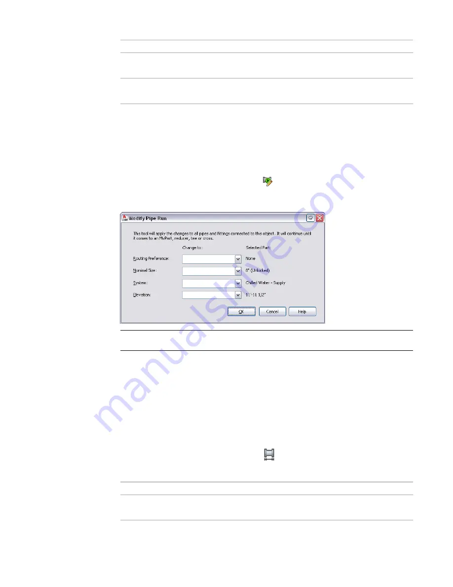
In the Modify Pipe Run dialog, change one or more settings (routing preference, nominal size,
system, and elevation) on the Modify Pipe Run dialog and click OK.
NOTE
You might be prompted to make a part substitution in the run. For more information, see
Breaking or Merging Pipe Segments
You can break or merge pipe segments in a pipe run. For example, you can break 1 pipe segment into 2 or
more adjacent segments. You can also merge 2 or more adjacent pipe segments to form 1 pipe segment. You
can apply the break or merge command to all or part of a pipe run.
To break or merge pipe segments in a pipe run
1
Select a pipe segment to break or merge.
2
Click Pipe tab
➤
Modify panel
➤
Pipe Length
page 268.
3
In the Pipe Length dialog, specify the segments to break or merge:
then…
If you want to…
select Apply to Pipe Run.
apply the length command to the entire pipe
run
Modifying Pipe | 329
Summary of Contents for 235B1-05A761-1301 - AutoCAD MEP 2010
Page 1: ...AutoCAD MEP 2010 User s Guide March 2009 ...
Page 22: ...4 ...
Page 86: ...68 ...
Page 146: ...128 ...
Page 180: ...162 ...
Page 242: ...Modifying the elevation of a duct 224 Chapter 6 Drawing HVAC Systems ...
Page 264: ...246 ...
Page 480: ...462 ...
Page 534: ...516 ...
Page 616: ...598 ...
Page 658: ...640 ...
Page 788: ...770 ...
Page 802: ...784 ...
Page 820: ...802 ...
Page 878: ...860 ...


