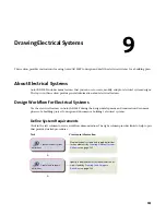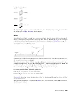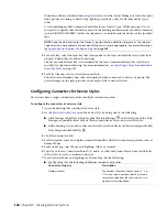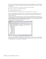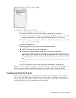
Drawing a branch
Cable tray and conduit components store properties such as connection type, size, system, and part type.
When you connect to existing cable tray or conduit runs to create branches, part properties are inherited,
providing a consistent method of drafting a layout. This ensures that you are creating intelligent building
system designs.
NOTE
Once you have completed your connections, you can
to test whether your connections
are valid.
You can also assign systems to cable tray and conduit to enable layouts to act together by maintaining the
same look and feel throughout the system. For example, a group of cable tray runs can represent a power
and lighting system, while another group of cable tray runs can represent a general system. For more
information, see
on page 93.
Auto Layout
As you draw cable tray or conduit runs, you lay out wireway geometry by specifying points in the drawing.
The software automatically inserts segments and fittings along the layout. You can control which parts are
inserted by configuring
before you begin drawing your wireway runs.
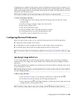
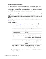
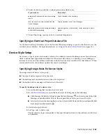
Cable Tray and Conduit Settings
You can use cable tray and conduit
to specify layout behavior as you draw wireway runs.
You can configure layout preferences to add annotation automatically, to specify default parts for auto-layout,
and to specify slopes for angled segments.
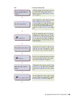
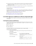
Electrical and Wire Ways Snaps
Like all building systems objects, electrical objects have connectors that enable them to connect intelligently
with each other, and transfer information along connected runs. As you draw electrical systems, you make
these intelligent connections using 2 types of AutoCAD MEP snaps:
■
Electrical Snaps.
Use these snaps to make connections when adding wires to devices and panels.
■
Wire Ways Snaps.
Use these snaps to make connections to cable tray, conduit, and electrical equipment
(also called Multi-view Parts or MvParts).
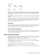
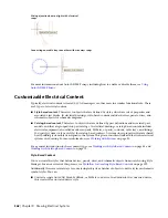
Like all AutoCAD MEP snaps, electrical snaps and wire ways snaps both have 2 subtypes:
■
End Connector Snaps.
Use these snaps to connect an object to an endpoint on another object.
■
Curve Connector Snaps.
Use these snaps to connect an object anywhere along the centerline of another
object.
Electrical and Wire Ways Snaps | 361
Summary of Contents for 235B1-05A761-1301 - AutoCAD MEP 2010
Page 1: ...AutoCAD MEP 2010 User s Guide March 2009 ...
Page 22: ...4 ...
Page 86: ...68 ...
Page 146: ...128 ...
Page 180: ...162 ...
Page 242: ...Modifying the elevation of a duct 224 Chapter 6 Drawing HVAC Systems ...
Page 264: ...246 ...
Page 480: ...462 ...
Page 534: ...516 ...
Page 616: ...598 ...
Page 658: ...640 ...
Page 788: ...770 ...
Page 802: ...784 ...
Page 820: ...802 ...
Page 878: ...860 ...


