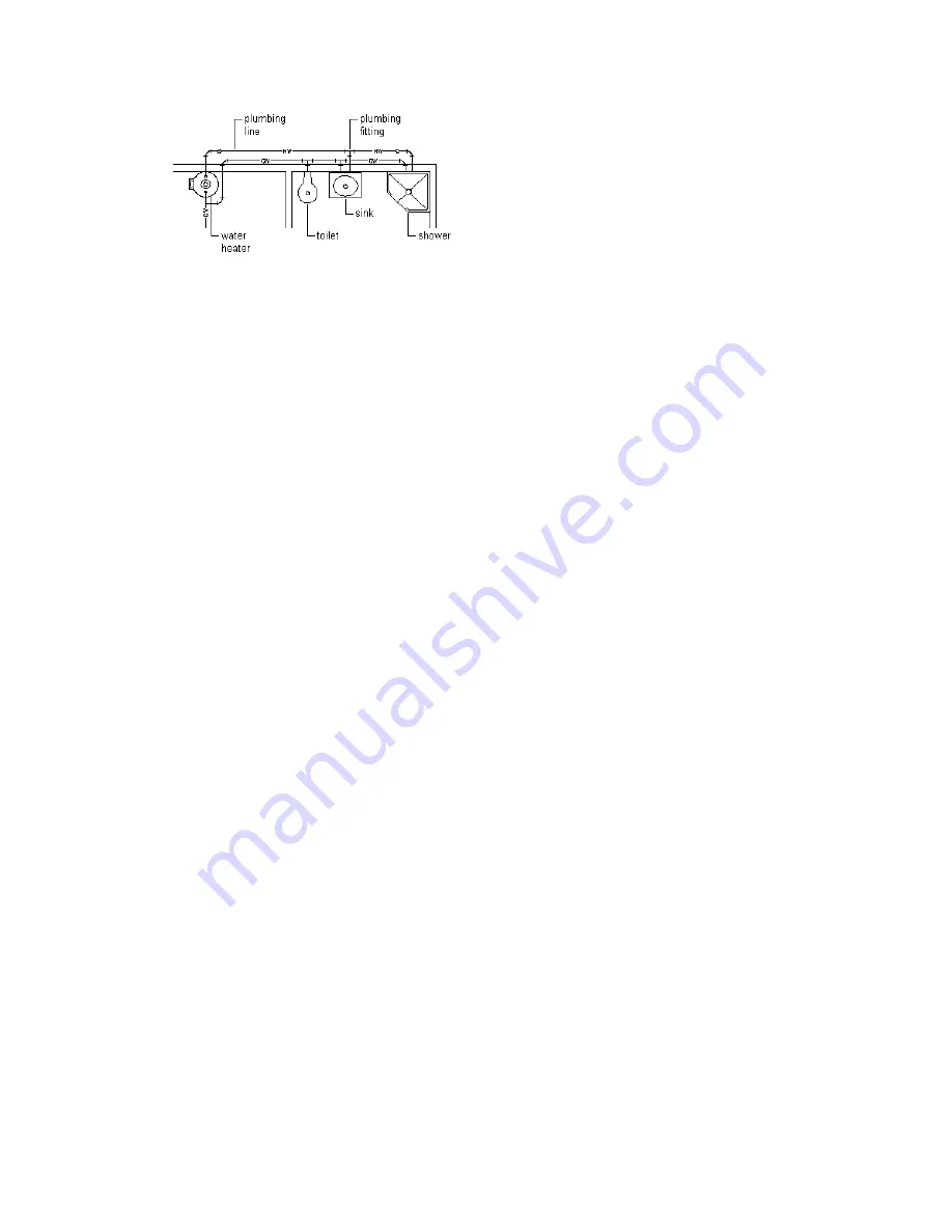
Domestic hot and cold water system
Before you draw a plumbing run, you specify a system for the segment on the plumbing line Properties
palette. As you draw the run, the software inserts plumbing fittings based on the default fittings configured
for that system definition. However, when necessary, you can override the default fittings for an individual
run or manually add an individual fitting. For information on specifying default fittings, see
Default Fittings for a Plumbing System Definition
on page 478.
Plumbing lines are 2-dimensional (2D) and can be system-based and style-based. For this reason, before you
add plumbing lines to a drawing, you should define the plumbing systems, plumbing line styles, and
plumbing fitting styles.
The plumbing line system determines the system type (i.e., Cold Water, Waste, or Fire Protection), the fittings
that the software inserts when necessary, and other properties. Systems help maintain consistency throughout
a run and across multiple drawings in a project. Once you define the plumbing systems, you select a system
on the Properties palette as you draw plumbing runs. For more information, see
on page 477.
The plumbing line style determines the appearance and function, such as the available standard sizes and
how crossing plumbing lines display in plan view. You can create plumbing line styles based on information
such as the size, type, and gauge of the material (i.e., Schedule 40 Carbon Steel or Copper Tube). As with
systems, once you define the styles, you can select a style on the Properties palette as you draw plumbing
runs.
Plumbing System Definitions
A plumbing system definition is typically named for the plumbing system for which it will be used, such as
domestic hot water or sanitary sewer. The settings for a system definition control many of the display
properties of a plumbing system. For example, a layer key style is assigned to a plumbing system definition,
which dictates the layer, color, and linetype for the plumbing system.
In the software, plumbing runs that have different systems cannot connect to each other without changing
the system for the connecting run. The exception is when the 2 system definitions comprise the same
. System groups allow different systems to connect to each other.
Plumbing Fittings
As you specify systems for equipment, fixtures, and plumbing line segments, AutoCAD MEP inserts plumbing
fittings based on those specified in the system definition. Therefore, you should specify default fittings for
the plumbing system definitions to use on a project. You can specify default fittings for 4 types of fittings:
elbows, tees, crosses, and transitions. For example, you can specify that the software place a base tee in the
drawing rather than a straight tee. For information on specifying default fittings, see
Fittings for a Plumbing System Definition
on page 478.
Plumbing System Definitions | 465
Summary of Contents for 235B1-05A761-1301 - AutoCAD MEP 2010
Page 1: ...AutoCAD MEP 2010 User s Guide March 2009 ...
Page 22: ...4 ...
Page 86: ...68 ...
Page 146: ...128 ...
Page 180: ...162 ...
Page 242: ...Modifying the elevation of a duct 224 Chapter 6 Drawing HVAC Systems ...
Page 264: ...246 ...
Page 480: ...462 ...
Page 534: ...516 ...
Page 616: ...598 ...
Page 658: ...640 ...
Page 788: ...770 ...
Page 802: ...784 ...
Page 820: ...802 ...
Page 878: ...860 ...


