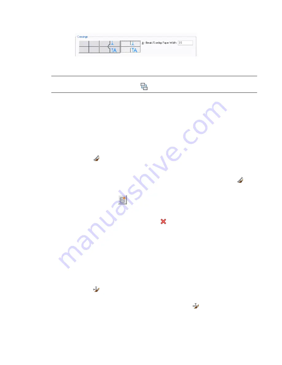
You can specify that the crossing lines are displayed as is, with an overlap, or with a break.
4
If you select the overlap style or break style, enter the paper width of the overlap or break, and
click OK.
TIP
To change the draw order of a selected line (for example, Send to Back), click Home tab
➤
Modify
panel
➤
Draworder drop-down
➤
Send To Back
.
Specifying Standard Sizes for a Plumbing Line Style
Before you draw a plumbing run, you select a style and specify a nominal size on the Properties palette. The
nominal sizes available on the Properties palette reflect the same sizes that you previously designated in
Style Manager.
To specify standard sizes for a plumbing line style
1
the Plumbing workspace activated
, open the style by doing one of the following:
■
Click Manage tab
➤
Style & Display panel
➤
Style Manager drop-down
➤
Plumbing Line
Styles
. In the left pane of Style Manager, click the style to specify, and in the right pane,
click the Standard Sizes tab.
■
Select a plumbing line that uses the style in the drawing, and click Plumbing Line
tab
➤
General panel
➤
Edit System Style drop-down
➤
Edit Plumbing Line Style
.
2
On the Standard Sizes tab, specify the standard (nominal) sizes for the plumbing line style:
■
To add a size, click
(New Size), enter a value, and press
ENTER
.
■
To modify a size, double-click the size, enter a different value, and press
ENTER
.
■
To delete a size, select the size, and click
(Remove Size).
Specifying Type and Subtype for a Plumbing Fitting Style
The type and subtype of a plumbing fitting style determine the default fitting behaviors for the style, for
example, whether a tee is long-radiused or short-radiused.
To specify the type and subtype for a plumbing fitting style
1
the Plumbing workspace activated
, open the style by doing one of the following:
■
Click Manage tab
➤
Style & Display panel
➤
Style Manager drop-down
➤
Plumbing Fitting
Styles
.
■
Select a plumbing fitting that uses the style in the drawing and click Plumbing Fitting
tab
➤
General panel
➤
Edit Style drop-down
➤
Edit Style
.
482 | Chapter 10 Drawing Plumbing Systems
Summary of Contents for 235B1-05A761-1301 - AutoCAD MEP 2010
Page 1: ...AutoCAD MEP 2010 User s Guide March 2009 ...
Page 22: ...4 ...
Page 86: ...68 ...
Page 146: ...128 ...
Page 180: ...162 ...
Page 242: ...Modifying the elevation of a duct 224 Chapter 6 Drawing HVAC Systems ...
Page 264: ...246 ...
Page 480: ...462 ...
Page 534: ...516 ...
Page 616: ...598 ...
Page 658: ...640 ...
Page 788: ...770 ...
Page 802: ...784 ...
Page 820: ...802 ...
Page 878: ...860 ...


