Adding Schematic Symbols in Orthographic Mode
, you add schematic symbols in the world coordinate system
(WCS). In the WCS, the X axis is horizontal, the Y axis is vertical, and the Z axis is perpendicular to the XY
plane.
You can use the
to guide your placement of symbols. You can also use the AutoCAD
®
Ortho mode
to restrict the cursor movement to the horizontal or vertical axes. The orthogonal alignment depends on
the current grid and snap settings. You can turn these tools on or off at any time.
Schematic symbols are connected to lines with anchors. For more information, see
page 519.
To add schematic symbols in orthographic mode
1
, start the add command by doing one of the following:
■
Open a schematic tool palette, and select a schematic symbol tool.
If necessary, scroll to display the tool. Because tools contain pre-configured properties for
the objects they create, you might not need or be able to specify some of the schematic
symbol properties referenced in this procedure.
■
Select a schematic line, and click Schematic Line tab
➤
General panel
➤
Insert Symbol
.
■
Click Home tab
➤
Build panel
➤
Schematic Symbol
.
■
Enter
symboladd
.
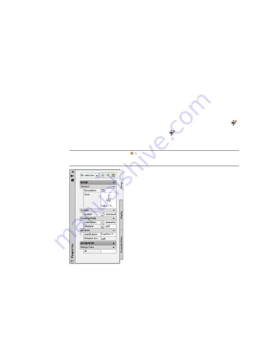
NOTE
On the Properties palette,
indicates a property is available only when you are adding
schematic symbols, not when you are modifying them.
Adding Schematic Symbols in Orthographic Mode | 527
Summary of Contents for 235B1-05A761-1301 - AutoCAD MEP 2010
Page 1: ...AutoCAD MEP 2010 User s Guide March 2009 ...
Page 22: ...4 ...
Page 86: ...68 ...
Page 146: ...128 ...
Page 180: ...162 ...
Page 242: ...Modifying the elevation of a duct 224 Chapter 6 Drawing HVAC Systems ...
Page 264: ...246 ...
Page 480: ...462 ...
Page 534: ...516 ...
Page 616: ...598 ...
Page 658: ...640 ...
Page 788: ...770 ...
Page 802: ...784 ...
Page 820: ...802 ...
Page 878: ...860 ...

