4
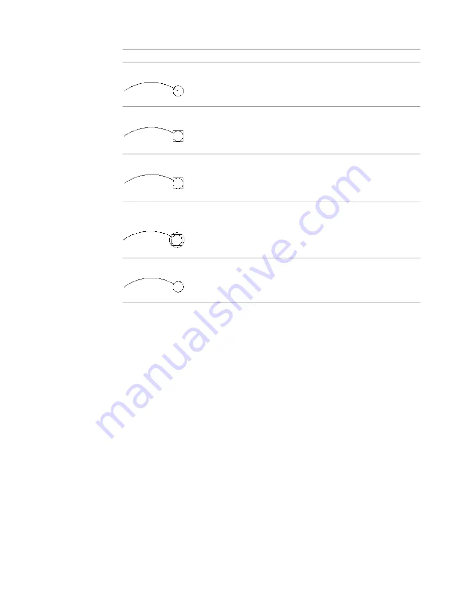
Select a cleanup method for schematic lines, wires, or plumbing lines, depending on the style:
then select…
If you want to end at the…
None.
connection point
Bounding Box.
edge of a surrounding hidden box
Inscribed Circle.
edge of an inscribed circle within a surrounding hidden box
Circumscribed Circle.
edge of a circumscribed circle outside a surrounding hidden
box
Trace Geometry.
at the edge
5
Click OK.
Existing content that uses the style is updated automatically. By default, any new content uses
the new method.
Defining the Views of a Style
Style-based content—devices, panels, plumbing fittings, schematic symbols, and multi-view parts
(MvParts)—are multi-view blocks (MvBlocks) that have smart connectors that enable them to connect
intelligently to form systems. An MvBlock is a custom object that can have different appearances in different
view directions. To define the appearance (or view) of style-based content, you assign a pre-drawn block to
a specified view in the style definition.
The number and types of blocks that you need depend on your requirements. For a schematic symbol style,
typically you can create one 2D block to represent the symbol in a plan view. If you need to create isometric
drawings, you can use this block to generate additional blocks for the 12 isometric views (that represent the
12 isometric view directions and orientations).
For other types of style-based content, you need to create the 2D and 3D blocks required to represent the
object in plan views and in model views. For example, a plumbing fitting style might require only a 2D
block to represent the fitting in a plan view. Similarly, a device style might require a 2D block to symbolically
represent the device in a plan view, but—if you need to create sections and elevations that display devices
in actual size—the device style will also require an MvBlock for use in a model view (and in other view
directions such as Front and Left).
604 | Chapter 13 Customizing Style-Based Content
Summary of Contents for 235B1-05A761-1301 - AutoCAD MEP 2010
Page 1: ...AutoCAD MEP 2010 User s Guide March 2009 ...
Page 22: ...4 ...
Page 86: ...68 ...
Page 146: ...128 ...
Page 180: ...162 ...
Page 242: ...Modifying the elevation of a duct 224 Chapter 6 Drawing HVAC Systems ...
Page 264: ...246 ...
Page 480: ...462 ...
Page 534: ...516 ...
Page 616: ...598 ...
Page 658: ...640 ...
Page 788: ...770 ...
Page 802: ...784 ...
Page 820: ...802 ...
Page 878: ...860 ...


