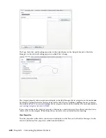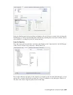
Then ...
If you want to scale the symbol block ...
select Override Scale, and for each coordinate direction (X,
Y, and Z), enter the scale factor to use to scale the block.
NOTE
If you select both this and Use Annotation
Scale, the block is scaled using the scale factors you
enter, and then the result is multiplied by the scale
factor for the
.
using a scale factor that you specify
When the symbol block is inserted in a drawing, it is first scaled so that its extents are one unit
(for example, one inch or one millimeter); it is then rescaled based on your selection here.
19
If you want to scale the center line block relative to the symbol block, for Center Line Block
Scale Factor, enter the scale factor.
For example, to scale the center line block to the same size as the symbol block, enter 1. To scale
it so it is 50% larger than the scaled symbol block, enter 1.5.
TIP
The preview image updates dynamically to assist you in specifying the desired scale factor for
the center line block.
20
Select the next symbol, and configure it using the same process.
21
If you want to add additional rise graphics or drop graphics, click Add, and configure an
additional symbol to be displayed in a specific rise condition or drop condition.
22
If you want to delete a symbol, click Remove.
NOTE
In a drawing, the display properties of the symbol block—including its visibility—are determined by the
settings of the Rise Drop display component for the current display representation. Similarly, the display properties
of the center line block are determined by the Center Line display component. This allows you to specify different
display properties for the symbols and their center lines. For information on configuring display settings, see
on page 134.
Connector Styles
Connector styles specify the rules that determine when connections are allowed between building systems
objects. The rules determine whether connections are allowed by comparing specific properties. For example,
when connecting 2 segments, typically you want to ensure the segments are the same size.
AutoCAD MEP includes the following connector styles:
■
Cable Tray
■
Conduit
■
Electric
■
HVAC
■
Pipe
■
Schematic
IMPORTANT
It is recommended that you keep the default configuration of the connector styles. Modifying the
styles might cause the software to work improperly.
616 | Chapter 13 Customizing Style-Based Content
Summary of Contents for 235B1-05A761-1301 - AutoCAD MEP 2010
Page 1: ...AutoCAD MEP 2010 User s Guide March 2009 ...
Page 22: ...4 ...
Page 86: ...68 ...
Page 146: ...128 ...
Page 180: ...162 ...
Page 242: ...Modifying the elevation of a duct 224 Chapter 6 Drawing HVAC Systems ...
Page 264: ...246 ...
Page 480: ...462 ...
Page 534: ...516 ...
Page 616: ...598 ...
Page 658: ...640 ...
Page 788: ...770 ...
Page 802: ...784 ...
Page 820: ...802 ...
Page 878: ...860 ...


