Customizing Schematic Symbol Content
This section provides information on several conversion tools you can use to create schematic symbol
content.
For information on creating style-based content manually, see
Workflow for Creating Style-Based Content
on page 599.
Converting Schematic Symbol Styles to Blocks
You can convert a set of schematic symbol styles to their individual components: the style settings and the
AutoCAD
®
blocks used by the style views. The output of the conversion process includes:
■
a set of drawings that contain the AutoCAD blocks. The process creates one drawing per view block per
style, so each drawing contains a single block definition.
■
a symbol conversion script (Custom Content File or CCF file) that contains the style settings. The script
contains not only the values for the style settings, but also the file path locations of the output drawings
that contain the AutoCAD blocks.
Typically, you use this process when you have a set of existing schematic symbol styles that you want to
customize. You convert the styles to their individual components, customize the components (the blocks
and the style settings in the script), and then use the modified script to convert the modified blocks to new
styles.
NOTE
This conversion process produces only the previously specified output. Your original schematic symbol
style drawings remain unchanged.
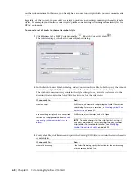
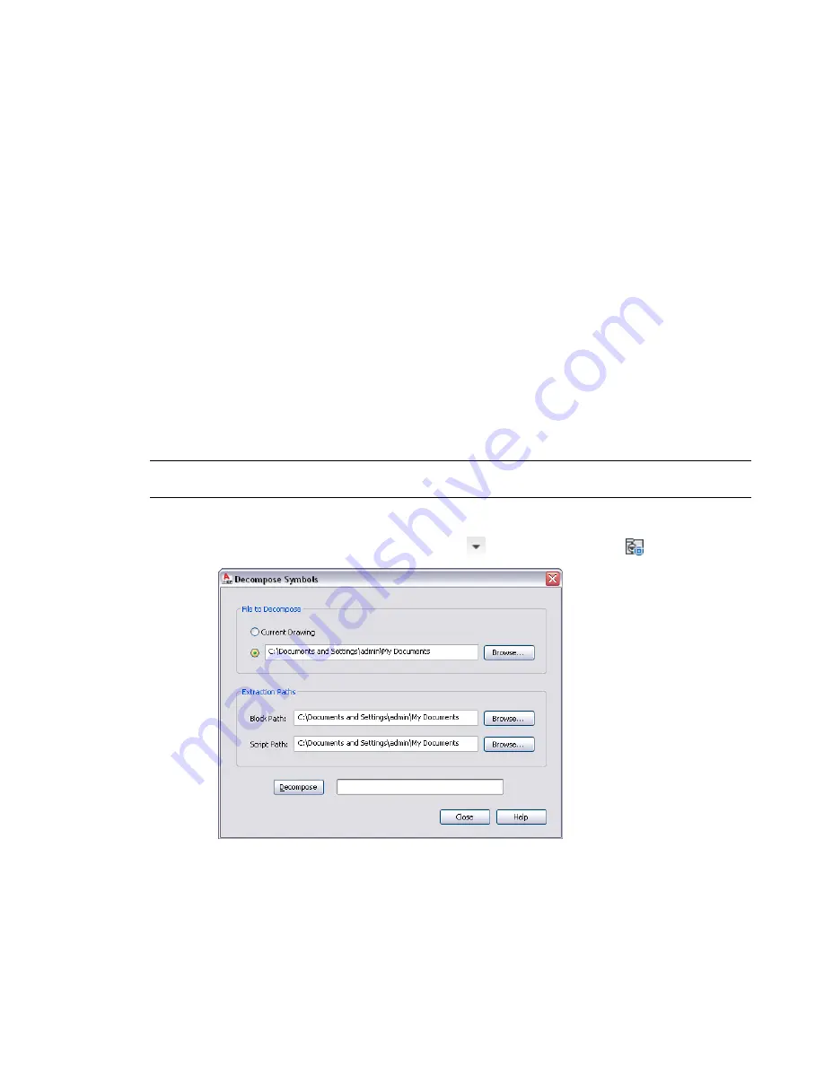
To convert a set of schematic symbol styles to their individual blocks
1
Click Manage tab
➤
MEP Content panel
➤
➤
Decompose Symbols
.
630 | Chapter 13 Customizing Style-Based Content
Summary of Contents for 235B1-05A761-1301 - AutoCAD MEP 2010
Page 1: ...AutoCAD MEP 2010 User s Guide March 2009 ...
Page 22: ...4 ...
Page 86: ...68 ...
Page 146: ...128 ...
Page 180: ...162 ...
Page 242: ...Modifying the elevation of a duct 224 Chapter 6 Drawing HVAC Systems ...
Page 264: ...246 ...
Page 480: ...462 ...
Page 534: ...516 ...
Page 616: ...598 ...
Page 658: ...640 ...
Page 788: ...770 ...
Page 802: ...784 ...
Page 820: ...802 ...
Page 878: ...860 ...


