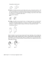
references one of the planes of the extent. To define a reference work plane, you select a modifier and a
source work plane that represents the plane direction you want to create. The extents, or boundary box, of
the feature is detected, and 2 valid reference work planes are available for selection. If the modifier is moved
or resized, the reference work plane is moved with it.
Creating a reference work plane
Geometry
You construct a model bit by bit, building shapes to add to it and using tools to cut away the portions of
the shapes you do not need. In Content Builder, these shapes are features of the part you are creating.
Geometry features are the basic building blocks for defining the size and shape of the model.
Geometry that you define is 2-dimensional (2D) and must be attached to a work plane. You can switch
between work planes to define different geometry. As you add geometry to a work plane, the geometry
features appear under the Geometry folder of the associated work plane.
WARNING
Avoid using basic AutoCAD
®
geometry commands. AutoCAD geometry is not valid for work planes
and cannot be used to create features for parametric part models.
Viewing geometry types
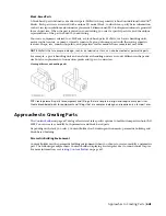
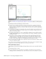
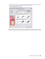
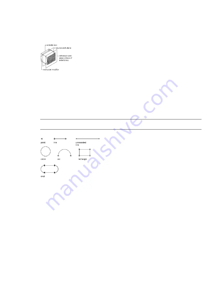
Content Builder provides 9 types of geometry you can use to build the model:
Point
Defined by an X and Y coordinate.
Line
Defined by a position and a direction; constrained by a start point and endpoint.
Unbounded Line
Defined by a position and a direction; infinite in length because it has no constraining
start point or endpoint.
Circle
Defined by a center point and a radius.
Arc
Defined by a center point and a radius; constrained by a start point and endpoint.
Rectangle
Defined by lines and points that are constrained to maintain start points and endpoints for each
side and perpendicular angle.
Oval
Defined by lines, arc, and points that are constrained to create 2 arcs tangent to 2 lines, with defined
start points and endpoints.
656 | Chapter 14 Customizing Catalog-Based Content
Summary of Contents for 235B1-05A761-1301 - AutoCAD MEP 2010
Page 1: ...AutoCAD MEP 2010 User s Guide March 2009 ...
Page 22: ...4 ...
Page 86: ...68 ...
Page 146: ...128 ...
Page 180: ...162 ...
Page 242: ...Modifying the elevation of a duct 224 Chapter 6 Drawing HVAC Systems ...
Page 264: ...246 ...
Page 480: ...462 ...
Page 534: ...516 ...
Page 616: ...598 ...
Page 658: ...640 ...
Page 788: ...770 ...
Page 802: ...784 ...
Page 820: ...802 ...
Page 878: ...860 ...

