Modifying the Part Size Name and View Blocks
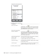
You can change the part size name and view blocks that are used to display a part size in a drawing. When
you change the 3D model block of a part size, you must regenerate the view blocks based on the new model
block to ensure correct display. It is possible to assign the same view block to multiple view directions, such
as front and back, depending on the part symmetry. You can also manually create individual view blocks
for a part size and attach them accordingly. For more information, see
Assigning Part Size Names and Views
on page 759.
Modifying the Preview Image
You can change the preview image of the part size. In doing so, you change the preview image for all part
sizes in the selected part family. You can regenerate a preview image based on a new 3D model block, or
attach a predefined image. For more information, see
Generating a Preview Image of a Block-Based MvPart
on page 760.
Modifying the Connectors
You can add, delete, and edit the connectors of a part size. You can change the size, type, and location of
the individual part size connector; however, the shape and domain are determined by the associated connector
defined for the part family. When you delete a connector, you are deleting the connector for all part sizes
in the part family. When you add a connector, you are adding a connector to all part sizes in the part family.
For more information, see
Adding Connectors to a Block-Based MvPart
on page 760.
IMPORTANT
The size and shape of every connector for a part size can be different. However, the number of
connectors must be the same for all part sizes of a part.
Modifying the Property Information
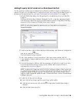
You can change the property information of a part size. You can add, delete, and edit custom properties for
a part size. When you add a custom property, you are adding a custom property to every part size in the
part family. You can modify custom property values as needed to enhance schedule data for the parts in
your drawing. For more information, see
Adding Property Set Information to a Block-Based MvPart
on page
763.
Working with Custom Parameter Groups
Custom parameters store additional, user-defined information about a part, such as manufacturer or product
information.
If you have a set of custom parameters that are common to multiple parts, you can create the custom
parameters for one part, save the parameters as a group in a Microsoft
®
Excel
®
file, and then retrieve the
group whenever you need to add the same parameters to additional parts.
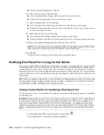
Saving Custom Parameters in Groups
When you save a group of custom parameters in a Microsoft
®
Excel
®
(XLS) file, you can save parameter
attributes as well as parameter values.
NOTE
Once you become familiar with how this feature saves the customer parameter data in an XLS file, you can
also create the files manually by copying the format. If you do so, make sure to use only the first worksheet in the
XLS file. When you add saved parameters to parts, the software reads only the data on the first worksheet.
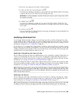
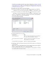
To save a set of custom parameters
1
In Content Builder, open the part that contains the custom parameters that you want to save.
766 | Chapter 14 Customizing Catalog-Based Content
Summary of Contents for 235B1-05A761-1301 - AutoCAD MEP 2010
Page 1: ...AutoCAD MEP 2010 User s Guide March 2009 ...
Page 22: ...4 ...
Page 86: ...68 ...
Page 146: ...128 ...
Page 180: ...162 ...
Page 242: ...Modifying the elevation of a duct 224 Chapter 6 Drawing HVAC Systems ...
Page 264: ...246 ...
Page 480: ...462 ...
Page 534: ...516 ...
Page 616: ...598 ...
Page 658: ...640 ...
Page 788: ...770 ...
Page 802: ...784 ...
Page 820: ...802 ...
Page 878: ...860 ...

