■
Click Manage tab
➤
Style & Display panel
➤
Style Manager drop-down
➤
Electrical System
Definitions
.
■
Click Manage tab
➤
Style & Display panel
➤
Style Manager drop-down
➤
Plumbing System
Definitions
.
■
Click Manage tab
➤
Style & Display panel
➤
Style Manager drop-down
➤
Schematic System
Definitions
.
2
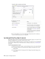
In the left pane, select the system, and, in the right pane, click the Rise and Drop tab.
3
For Rise and Drop Style, select a style from the list.
You can select from the rise/drop styles in the current drawing that are appropriate based on
the system type of the system. For example, if the system type of the system is Cable Tray, you
can select a cable tray rise/drop style, but you cannot select a conduit rise/drop style.
NOTE
You might need to regenerate your drawing to display rise graphics and drop graphics for systems that
have existing runs drafted.
Specifying the Display Properties of a System
Display properties control how parts that belong to the system are displayed in your layout. System definitions
use the display properties configured for the display representations, but you can override display settings
to customize display for a system definition.
For information on the AutoCAD MEP display system, see
To specify the display properties of a system
1
Within the domain-specific workspace, open the Style Manager and access the system definitions:
■
Click Manage tab
➤
Style & Display panel
➤
Style Manager drop-down
➤
HVAC System
Definitions
.
■
Click Manage tab
➤
Style & Display panel
➤
Style Manager drop-down
➤
Piping System
Definitions
.
■
Click Manage tab
➤
Style & Display panel
➤
Style Manager drop-down
➤
Electrical System
Definitions
.
■
Click Manage tab
➤
Style & Display panel
➤
Style Manager drop-down
➤
Plumbing System
Definitions
.
■
Click Manage tab
➤
Style & Display panel
➤
Style Manager drop-down
➤
Schematic System
Definitions
.
2
In the left pane, select the system, and, in the right pane, click the Display Properties tab.
3
Under Display Representations, select the display representation you want to override.
4
For the selected display representation, select Style Override.
5
In the Display Properties dialog, modify the display properties of the display components as
needed.
To edit each property, click its field.
6
Click OK twice.
Specifying the Display Properties of a System | 99
Summary of Contents for 235B1-05A761-1301 - AutoCAD MEP 2010
Page 1: ...AutoCAD MEP 2010 User s Guide March 2009 ...
Page 22: ...4 ...
Page 86: ...68 ...
Page 146: ...128 ...
Page 180: ...162 ...
Page 242: ...Modifying the elevation of a duct 224 Chapter 6 Drawing HVAC Systems ...
Page 264: ...246 ...
Page 480: ...462 ...
Page 534: ...516 ...
Page 616: ...598 ...
Page 658: ...640 ...
Page 788: ...770 ...
Page 802: ...784 ...
Page 820: ...802 ...
Page 878: ...860 ...

