For more information on the display system, see
on page 134.
Auto-layout
As you draw duct runs, you lay out the duct run geometry by specifying points in the drawing. The software
automatically inserts duct segments and fittings along the layout. You can control which ducts and fittings
are inserted by configuring duct layout preferences before you begin drawing duct runs.
The software includes many tools to streamline the layout of a duct run. You can use the compass to specify
an angle, and you can use tracking lines to align a component with another object or line. You can use snaps
to connect to duct objects, or to a geometric point on an object or line.
HVAC System Settings
There are several settings you can configure to control the construction, display, and annotation of duct
systems. The primary settings are:
■
Duct layout preferences: These settings specify routing and auto-layout behavior, and can be used to
automatically add items such as labels and insulation to duct runs.
■
HVAC system definitions: These settings specify duct size calculation parameters and duct display
information, such as layer key settings, rise and drop display style, and display properties.
The duct layout preferences are applied to all duct runs as you draw them. When you add a duct run, you
specify a system definition. The duct layout preferences specify what parts and connections are used in a
duct run, and the system definition controls the display.
For information on working with duct settings, see
Configuring Duct System Settings
on page 174.
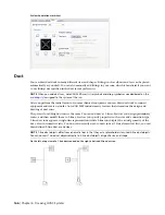
Duct Fitting Vanes
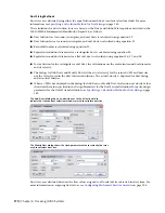
You can access turning vane information for duct fittings from the Vanes tab in the Properties dialog. The
Vanes tab has only one control, Enable Vanes. Use the Vanes tab to specify whether an individual fitting
should display turning vanes.
NOTE
If you want to display turning vanes, you must add vanes to the duct fitting. Select the duct fitting, click
Duct Fitting tab
➤
Duct Vanes panel
➤
Add Vanes
. The vane graphic is added to the fitting style. The Enable
Vanes control defines if an individual fitting should display vanes.
168 | Chapter 6 Drawing HVAC Systems
Summary of Contents for 235B1-05A761-1301 - AutoCAD MEP 2010
Page 1: ...AutoCAD MEP 2010 User s Guide March 2009 ...
Page 22: ...4 ...
Page 86: ...68 ...
Page 146: ...128 ...
Page 180: ...162 ...
Page 242: ...Modifying the elevation of a duct 224 Chapter 6 Drawing HVAC Systems ...
Page 264: ...246 ...
Page 480: ...462 ...
Page 534: ...516 ...
Page 616: ...598 ...
Page 658: ...640 ...
Page 788: ...770 ...
Page 802: ...784 ...
Page 820: ...802 ...
Page 878: ...860 ...


