1
Open the Add Duct dialog:
then...
If you want to...
select the MvPart and click the Add Duct grip for the connection
you want to draw from.
draw duct directly from an MvPart
select the 1-Line tool on the Duct tool palette in the HVAC tool
palette group.
draw duct from any point
2
In the Add Ducts dialog, verify that Connection Type and Shape are set to Undefined.
3
Specify a type for System.
4
Specify a defined elevation for Elevation, or enter a height value for Elevation. If you are drawing
from an Add Duct grip on an MvPart, the duct automatically assumes the elevation from the
MvPart.
5
Specify points to place the duct run.
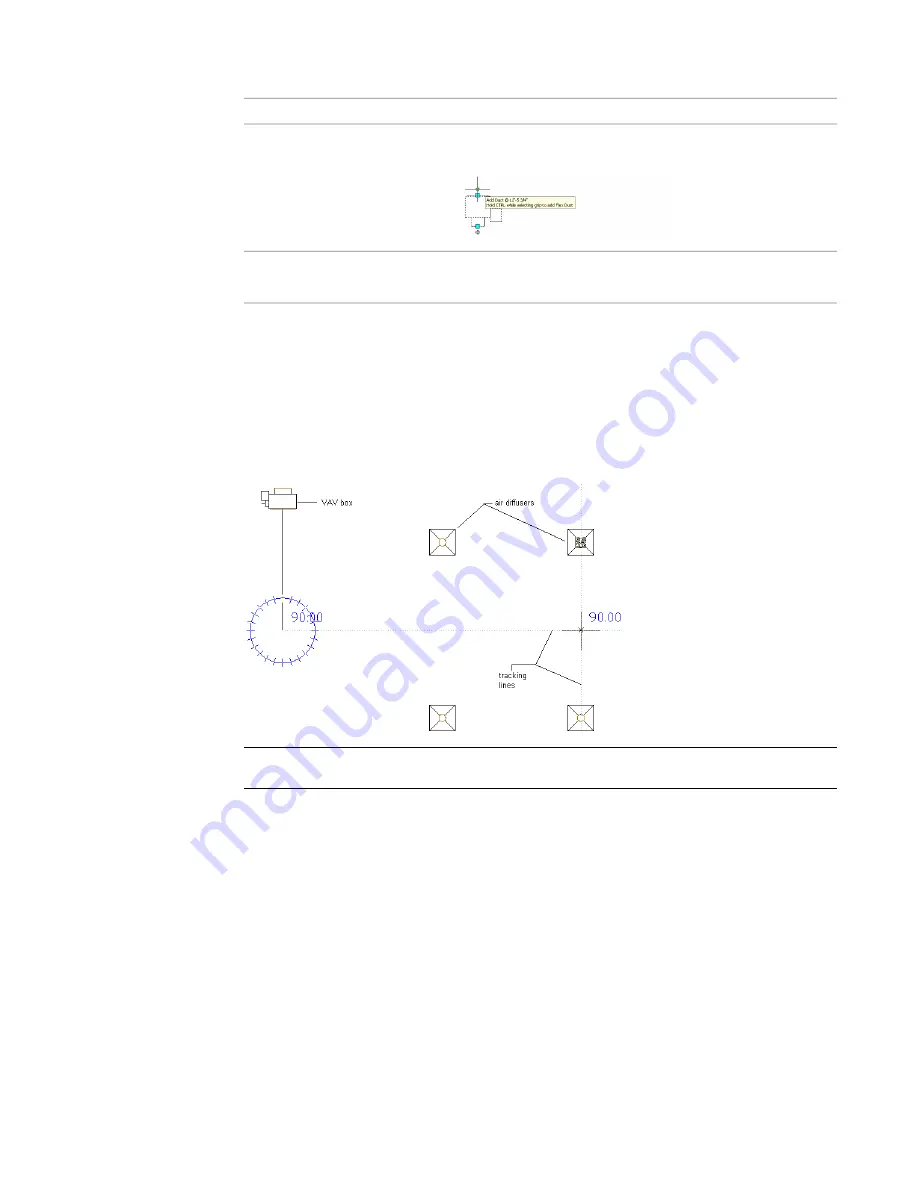
Drawing 1-line duct, top view. Note how AutoCAD MEP snaps and tracking lines can
be used to align duct geometry with other objects.
NOTE
To align duct with parts or building geometry, use tracking as you draw. Tracking works with
both object snaps and AutoCAD MEP snaps.
Use AutoCAD MEP snaps when connecting a duct run to an MvPart. If you are connecting to a
part, especially one on a different elevation than the duct run, more than one routing option
may be offered. It can be helpful to use 2 viewports to get an accurate preview of each routing
option. For example, the Aecb Model drawing template includes a Work layout tab where the
workspace is configured for 2 viewports.
202 | Chapter 6 Drawing HVAC Systems
Summary of Contents for 235B1-05A761-1301 - AutoCAD MEP 2010
Page 1: ...AutoCAD MEP 2010 User s Guide March 2009 ...
Page 22: ...4 ...
Page 86: ...68 ...
Page 146: ...128 ...
Page 180: ...162 ...
Page 242: ...Modifying the elevation of a duct 224 Chapter 6 Drawing HVAC Systems ...
Page 264: ...246 ...
Page 480: ...462 ...
Page 534: ...516 ...
Page 616: ...598 ...
Page 658: ...640 ...
Page 788: ...770 ...
Page 802: ...784 ...
Page 820: ...802 ...
Page 878: ...860 ...


