Description
Setting
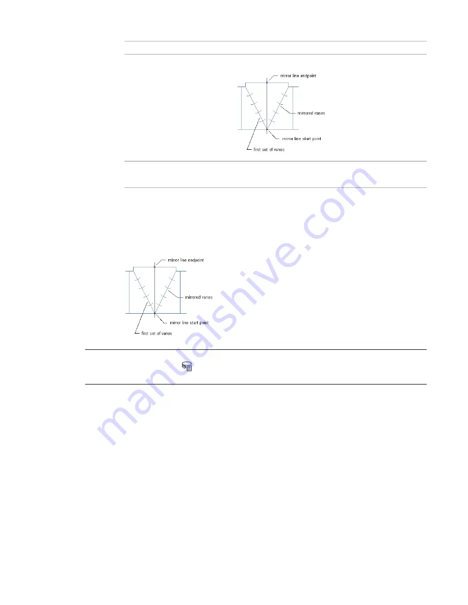
for tees; mirror the first set of vanes around a specified line
mirror current vanes
displays vane path on the fitting; specify no to not show the vane
path
keep vane path
5
When prompted to select a start point, specify the inside corner of the fitting.
6
Specify the outside corner of the fitting as the vane path endpoint.
Vanes are added to each fitting of the same size and subtype.
7
If you are mirroring vanes, specify the start and endpoints of the mirror line.
A second set of vanes is added to the tee.
TIP
To apply or remove turning vanes on selected fittings, select a fitting, and click Duct Fitting tab
➤
Modify
panel
➤
Duct Fitting Properties
. In the Duct Fitting Properties dialog, click the Vanes tab, and select or clear
Enable Vanes.
Creating a Custom Duct Fitting
You can create a custom fitting when a required fitting is not available from the part catalog or you have a
unique design situation. You create custom fittings by converting AutoCAD
®
lines, arcs, and polylines into
AutoCAD MEP objects with connectors. Part properties, such as size, shape, and system definition are
inherited from the connecting parts to maintain system integrity. Custom fittings are style-based objects
accessible through the Style Manager. Each custom fitting you create represents a single style.
Adding Duct | 215
Summary of Contents for 235B1-05A761-1301 - AutoCAD MEP 2010
Page 1: ...AutoCAD MEP 2010 User s Guide March 2009 ...
Page 22: ...4 ...
Page 86: ...68 ...
Page 146: ...128 ...
Page 180: ...162 ...
Page 242: ...Modifying the elevation of a duct 224 Chapter 6 Drawing HVAC Systems ...
Page 264: ...246 ...
Page 480: ...462 ...
Page 534: ...516 ...
Page 616: ...598 ...
Page 658: ...640 ...
Page 788: ...770 ...
Page 802: ...784 ...
Page 820: ...802 ...
Page 878: ...860 ...


