NOTE
If the routing preference for one or more of the pipes does not specify a required pipe type
or fitting, the Choose a Part dialog prompts you to specify a different part. See
on
page 303 for more information.
7
If you make changes on the Properties palette, the following guidelines apply:
■
A change to a property that guides the placement of the baseline pipe, such as Justification
or Compass, applies only to the baseline pipe.
■
A change that affects the physical characteristics of a pipe segment being created, such as
Size or Insulation Thickness, affects all pipe segments in the run.
■
A new Elevation value modifies the elevation of all pipes being routed. The distance between
the pipes is maintained over the elevation change unless it results in a conflict.
■
You cannot change some properties, including System, Routing Preferences, Fitting Settings,
and Layout Method, while the
PipeParallel
command is active.
8
To designate a different pipe as the baseline pipe, enter
b
.
The current routing options, such as Justification or Compass, apply to the new baseline pipe.
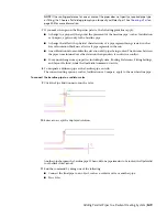
To connect the baseline pipe to a radiator valve
9
Click the Pipe End Connector on the valve.
10
Enter
a
to accept the displayed solution.
Another pipe becomes the baseline pipe. When only one pipe remains to be routed, the
PipeParallel
tool behaves like
PipeAdd
.
11
End the command by doing one of the following:
■
Connect the final pipe to an object, such as a radiator valve or another pipe.
■
Press
Enter
.
Adding Parallel Pipes to a Radiant Heating System | 349
Summary of Contents for 235B1-05A761-1301 - AutoCAD MEP 2010
Page 1: ...AutoCAD MEP 2010 User s Guide March 2009 ...
Page 22: ...4 ...
Page 86: ...68 ...
Page 146: ...128 ...
Page 180: ...162 ...
Page 242: ...Modifying the elevation of a duct 224 Chapter 6 Drawing HVAC Systems ...
Page 264: ...246 ...
Page 480: ...462 ...
Page 534: ...516 ...
Page 616: ...598 ...
Page 658: ...640 ...
Page 788: ...770 ...
Page 802: ...784 ...
Page 820: ...802 ...
Page 878: ...860 ...


