Circuit Manager
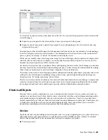
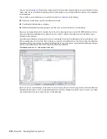
To search for a panel, enter the panel name above the list. You can view the properties of each circuit in the
Circuit Manager.
■
Expand a specific panel to list all circuits by system type assigned to that panel.
■
Expand a circuit type under a panel (for example, Power and Lighting) to list all circuits of that type
assigned to the panel.
The right pane of the Circuit Manager lists information about the circuits in your drawing (or in all drawings,
if you are using the electrical project database). The information is based on what you selected in the left
pane—a panel, circuit type, or circuit. Overloaded circuits display in red.
While you can modify some circuit properties using the Circuit Manager, other properties are displayed for
reference and are read-only. For example, you can modify the name and description of a circuit, but the
number of poles and phases (for ANSI) are read-only.
For circuits whose system type is specified as Power and Lighting, you can use the Circuit Manager to calculate
wire sizes based on the circuit rating. When checking wire sizes, you have the option of automatically resizing
them if they are undersized or oversized when compared to the calculated sizes.
The header section of the Circuit Manager contains information from the panel object properties and circuit
settings for the selected panel, including voltage, phases/wires, panel rating and type, main rating size,
design capacity, AIC rating, mounting, and enclosure.
The footer section contains calculations for connected loads and demand factor, including a summary and
totals for connected loads for each load category, totals for each load category multiplied by the demand
factor, demand load total and available spare capacity, and load distribution among the phases.
Electrical Objects
Electrical objects are the components you use to design electrical systems. Devices, panels, and wires are
referred to as electrical objects. Most objects, such as receptacles, switches, and telecommunications outlets,
are typically displayed symbolically, and are not drawn to scale in plan view. Objects such as lights also
display symbolically, yet they are scaled to their actual envelope dimensions in plan view. This enables you
to easily place the lights to achieve your desired lighting density, and it also enables you to check for
interferences among larger electrical components and surrounding systems.
Devices
Typically, the first step in drafting an electrical plan, such as a power or lighting plan, is to place the devices
and panels in the appropriate locations on the floor plan. AutoCAD MEP provides a library of electrical
devices that includes most of the elements that you need to complete your plans:
■
Power receptacles
Electrical Objects | 357
Summary of Contents for 235B1-05A761-1301 - AutoCAD MEP 2010
Page 1: ...AutoCAD MEP 2010 User s Guide March 2009 ...
Page 22: ...4 ...
Page 86: ...68 ...
Page 146: ...128 ...
Page 180: ...162 ...
Page 242: ...Modifying the elevation of a duct 224 Chapter 6 Drawing HVAC Systems ...
Page 264: ...246 ...
Page 480: ...462 ...
Page 534: ...516 ...
Page 616: ...598 ...
Page 658: ...640 ...
Page 788: ...770 ...
Page 802: ...784 ...
Page 820: ...802 ...
Page 878: ...860 ...


