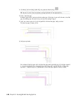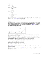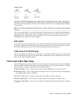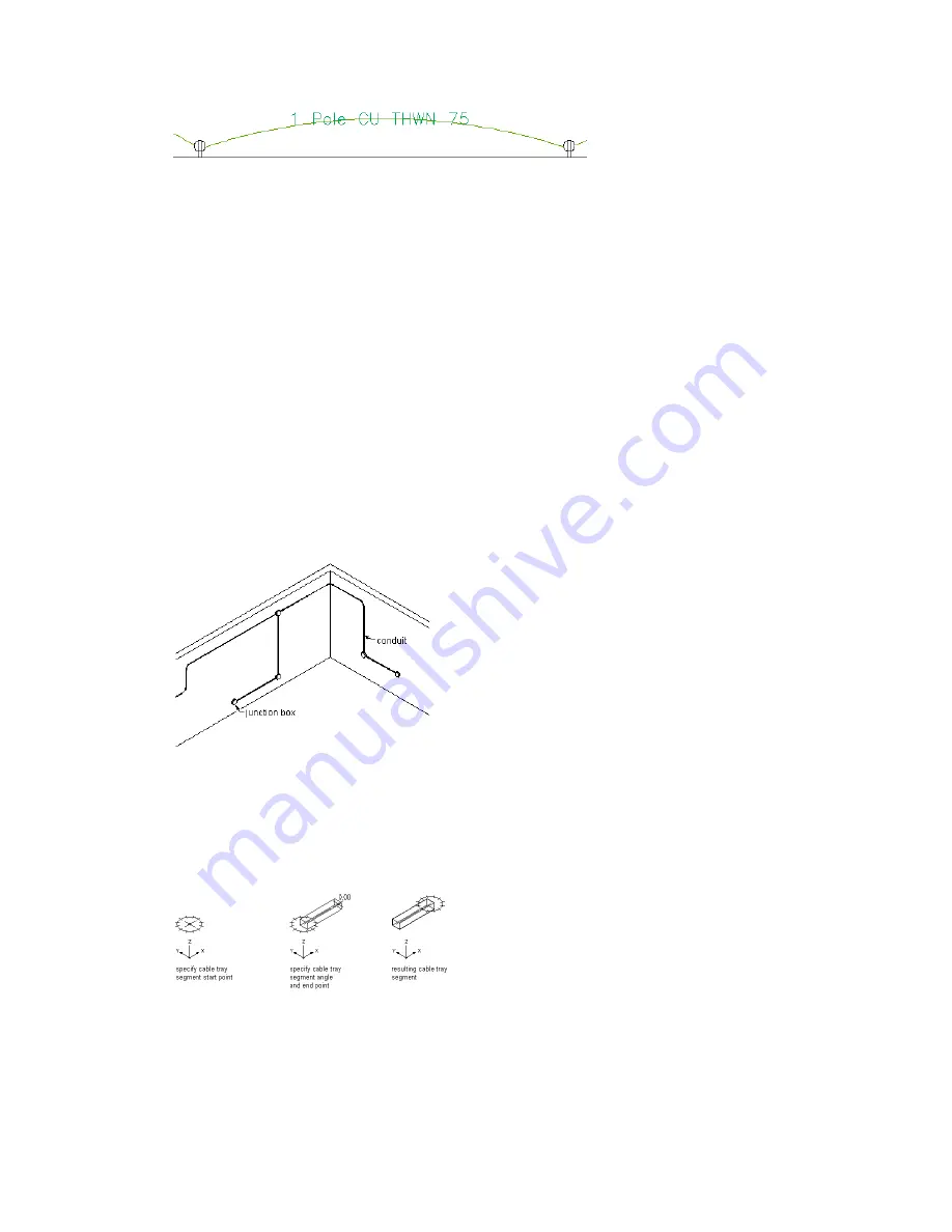
A wire segment with a label indicating the wire style
Wire Size Calculations
You can automatically calculate wire sizes for circuited wire runs. As you add wire, you can use the instant
sizing tool to automatically calculate wire sizes based on the circuit rating. You can also use the Circuit
Manager to calculate wire sizes for any wires assigned to a circuit. Wire sizes are calculated based on the
National Electrical Code (NEC) 2002 Handbook: Table 250.122 for ground conductors, and Table 310.16 for
current-carrying conductors.
For more information, see
on page 412,
on page 441, and
Wire Sizes Using the Circuit Manager
on page 425.
Cable Trays and Conduits
You can draw cable tray and conduit runs in order to form complete electrical networks.
In the software, a run is the cable tray or conduit parts that encase or support wires, bringing them from
one point, such as a junction box or a panel, to another point, such as the junction with another run. A
network is a group of interconnected cable tray or conduit runs.
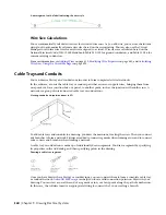
Viewing conduit and junction boxes in 3D
To add cable trays and conduits to a drawing, you draw the main runs, locating the risers. Then you connect
any branches to form a network. Fittings are added to connect segments when forming a run, and to connect
runs to risers and branches when forming a network.
A cable tray or conduit run is made up of individually drawn segments. You draw a segment by specifying
its properties in the Add dialog, and then specifying points in the drawing.
Drawing a cable tray segment
Once you have drawn the cable tray or conduit runs, you can connect them to form a complete cable tray
or conduit network.
can help you locate valid connection points on objects in your
drawing. You can start a run at the end of a segment or run, or at any point along the path of another run.
In this case, the software inserts an appropriate fitting to connect the 2 runs, creating a branch.
360 | Chapter 9 Drawing Electrical Systems
Summary of Contents for 235B1-05A761-1301 - AutoCAD MEP 2010
Page 1: ...AutoCAD MEP 2010 User s Guide March 2009 ...
Page 22: ...4 ...
Page 86: ...68 ...
Page 146: ...128 ...
Page 180: ...162 ...
Page 242: ...Modifying the elevation of a duct 224 Chapter 6 Drawing HVAC Systems ...
Page 264: ...246 ...
Page 480: ...462 ...
Page 534: ...516 ...
Page 616: ...598 ...
Page 658: ...640 ...
Page 788: ...770 ...
Page 802: ...784 ...
Page 820: ...802 ...
Page 878: ...860 ...


