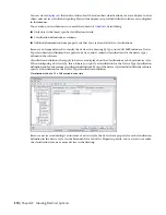
When the software calculates loads in
or in the Circuit Manager, it totals the loads
into 3 groups according to device type: lighting, receptacles, and, for all other device types,
other.
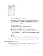
A corresponding modify command is available for each device type. While pressing
Ctrl
, you
can press
A
to quickly select all of the objects in the drawing, and then enter a modify command,
such as LIGHTINGMODIFY, to filter the selection set to include only the devices of the specified
type.
NOTE
Keep the classification for the Device Type classification definition the same as the value for
Type unless you have added a custom classification that is more appropriate. For more information,
see
Specifying Classifications for Device Styles
on page 369.
5
For Layer Key, select the layer key that corresponds to the layer on which devices of this style
are placed when they are added to drawings.
The list of available layer keys is determined by the layer standard and layer key style that is
specified for the current drawing. For more information, see
Specifying a Layer Standard and a
on page 134.
6
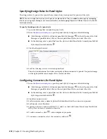
For Wire Cleanup, select a wire cleanup method.
This selection determines how wires are displayed when connected to devices or panels. The
preview image on the right provides an example of the current selection.
Configuring Connectors for Device Styles
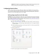
Devices can have a single connection point or multiple connection points.
To configure the connectors of a device style
1
Open the drawing that contains the device style.
2
, open the device style by doing one of the following:
■
Click Manage tab
➤
Style & Display panel
➤
Style Manager
. In the left pane of the Style
Manager, expand Electrical Objects, then expand Device Styles, and select the style.
■
In the drawing, select a device that uses the style, and click Device tab
➤
General panel
➤
Edit
Style drop-down
➤
Edit Style
.
3
Click the Connectors tab.
4
For Description, enter a descriptive name that identifies what the connector represents, such as
Normal Power.
5
For System Type, select Power and Lighting, Other, or General.
6
Specify a value for Connection Point X, Y, and Z, or click Add Center Points from View Blocks
in Top View to create a centered connector.
7
If you selected Power and Lighting for System Type, do the following:
■
Specify values for the following additional connector properties:
Description
Connector Property
The number of poles on the connector: 1, 2, or
3. You can select a number, select By Circuit to
Number of poles
retrieve the value from the circuit when it is as-
signed, or select Undefined.
368 | Chapter 9 Drawing Electrical Systems
Summary of Contents for 235B1-05A761-1301 - AutoCAD MEP 2010
Page 1: ...AutoCAD MEP 2010 User s Guide March 2009 ...
Page 22: ...4 ...
Page 86: ...68 ...
Page 146: ...128 ...
Page 180: ...162 ...
Page 242: ...Modifying the elevation of a duct 224 Chapter 6 Drawing HVAC Systems ...
Page 264: ...246 ...
Page 480: ...462 ...
Page 534: ...516 ...
Page 616: ...598 ...
Page 658: ...640 ...
Page 788: ...770 ...
Page 802: ...784 ...
Page 820: ...802 ...
Page 878: ...860 ...

