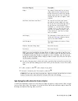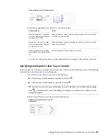
TIP
To change the draw order of a selected wire, click Home tab
➤
Modify panel
➤
Bring to Front drop-down
and then choose one of the options offered.
To specify annotation for a wire style
1
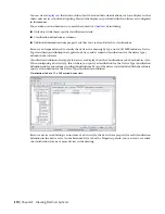
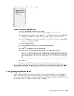
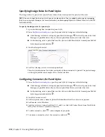
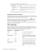
Open the style by doing one of the following:
■
click Manage tab
➤
Style & Display panel
➤
Style Manager
. In the left pane of the Style Manager, expand Electrical Objects, then expand Wire Styles,
and select the style.
■
In the drawing, select a wire that uses the style and click Wire tab
➤
General panel
➤
Edit
Style drop-down
➤
Edit Style
.
2
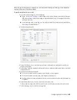
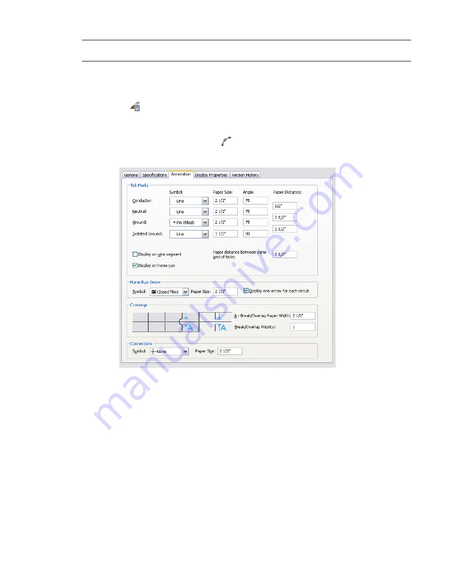
Click the Annotation tab.
3
Under Tick Marks, select a symbol type, and enter a tick mark size and angle for conductor,
neutral, and ground.
4
For Distance, enter the spacing for tick marks between conductor and neutral wires, or neutral
and ground wires.
5
Specify how to display tick marks:
■
To show tick marks on each segment, select Display on wire segment.
■
To show tick marks on home runs, select Display on home run.
■
For Paper distance between same kind of ticks, enter the distance between the tick marks on
a segment.
6
Under Home Run Arrow, select an arrow style, and enter a size.
To show only one home run arrow for each circuit, select Display one arrow for each circuit.
7
Under Crossings, select a style for crossing wires.
Configuring Styles for Wires | 375
Summary of Contents for 235B1-05A761-1301 - AutoCAD MEP 2010
Page 1: ...AutoCAD MEP 2010 User s Guide March 2009 ...
Page 22: ...4 ...
Page 86: ...68 ...
Page 146: ...128 ...
Page 180: ...162 ...
Page 242: ...Modifying the elevation of a duct 224 Chapter 6 Drawing HVAC Systems ...
Page 264: ...246 ...
Page 480: ...462 ...
Page 534: ...516 ...
Page 616: ...598 ...
Page 658: ...640 ...
Page 788: ...770 ...
Page 802: ...784 ...
Page 820: ...802 ...
Page 878: ...860 ...

