2
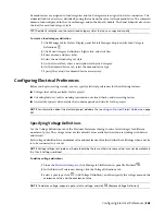
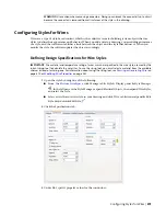
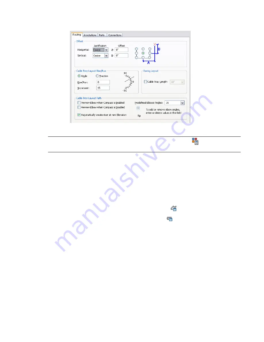
In the Layout Preferences dialog, click the Routing tab.
3
Click Cable Tray Length or Conduit Length, specify the segment length, and click OK.
TIP
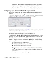
As you draw, you can also access and change the layout preferences by clicking
(Preferences) in the Add
dialog.
Specifying Annotation for Cable Tray or Conduit
You can specify labels or flow arrows to be added to cable tray or conduit runs as you draw them. For cable
tray runs, you can also specify the hatch pattern to apply. You can specify vertical or 45-degree lines and
the line spacing to use.
To specify annotation for cable tray or conduit layout
1
■
Click Manage tab
➤
Preferences panel
➤
Cable Tray
.
■
Click Manage tab
➤
Preferences panel
➤
Conduit
.
2
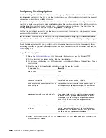
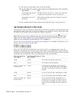
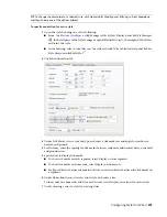
In the Layout Preferences dialog, click the Annotations tab.
3
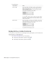
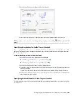
To specify a cable tray pattern, under Cable Tray Pattern, select a type of line pattern, and enter
a value for Spacing.
To assist you, the preview image on the right provides an example of the current selections.
4
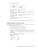
Under Labels and Flow Arrows, select a style and specify a layout method. You can define labels
only, flow arrows only, or both.
Specifying Default Parts for Cable Tray or Conduit
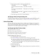
Use this procedure to specify the parts and fittings that are inserted automatically as you draw a cable tray
or conduit run.
Configuring Layout Preferences for Cable Tray or Conduit | 379
Summary of Contents for 235B1-05A761-1301 - AutoCAD MEP 2010
Page 1: ...AutoCAD MEP 2010 User s Guide March 2009 ...
Page 22: ...4 ...
Page 86: ...68 ...
Page 146: ...128 ...
Page 180: ...162 ...
Page 242: ...Modifying the elevation of a duct 224 Chapter 6 Drawing HVAC Systems ...
Page 264: ...246 ...
Page 480: ...462 ...
Page 534: ...516 ...
Page 616: ...598 ...
Page 658: ...640 ...
Page 788: ...770 ...
Page 802: ...784 ...
Page 820: ...802 ...
Page 878: ...860 ...

