6
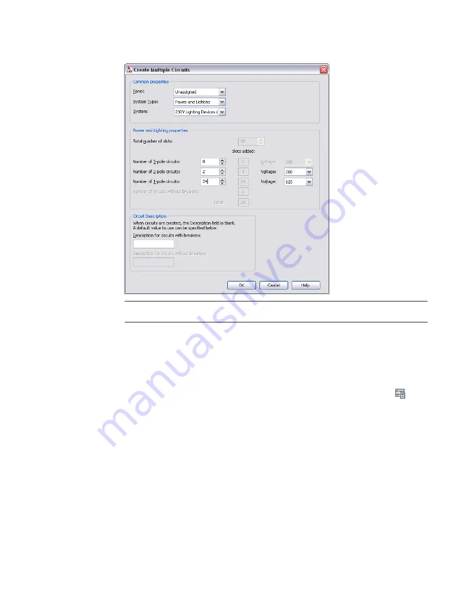
Under <System Type> Properties, specify the number of 1-pole, 2-pole, and 3-pole circuits and
their respective voltages.
NOTE
After adding new circuits, update the panel schedules in your drawing. See
on page 459 for more information.
Configuring a Circuit
After you
, configure circuit properties, such as voltage, rating, load category, and system.
1
Open the drawing that contains the circuits and select a device.
2
Click Device tab
➤
Circuits panel
➤
Circuit Manager drop-down
➤
Circuit Manager
.
3
In the left pane of the Circuit Manager, expand the panel, expand the branch (for example,
Power and Lighting), and select the circuit to be configured.
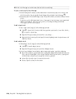
To edit properties for multiple circuits, select the branch in the left pane that contains the
circuits. On the right pane, use
Shift
or
Ctrl
to select multiple rows in the circuit list view.
4
Double-click the circuit property field in the right pane.
5
Enter the new information, or select a new property from the list.
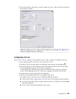
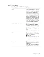
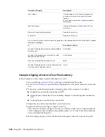
Depending on the system type, you can modify the following properties:
■
Name: Specify a name, using
for new circuits using electrical preferences.
■
Description: Typically a brief description of the type of devices and the area of the building
this circuit will service.
■
System: The electrical system definition for the circuit.
Using Circuits | 387
Summary of Contents for 235B1-05A761-1301 - AutoCAD MEP 2010
Page 1: ...AutoCAD MEP 2010 User s Guide March 2009 ...
Page 22: ...4 ...
Page 86: ...68 ...
Page 146: ...128 ...
Page 180: ...162 ...
Page 242: ...Modifying the elevation of a duct 224 Chapter 6 Drawing HVAC Systems ...
Page 264: ...246 ...
Page 480: ...462 ...
Page 534: ...516 ...
Page 616: ...598 ...
Page 658: ...640 ...
Page 788: ...770 ...
Page 802: ...784 ...
Page 820: ...802 ...
Page 878: ...860 ...

