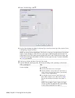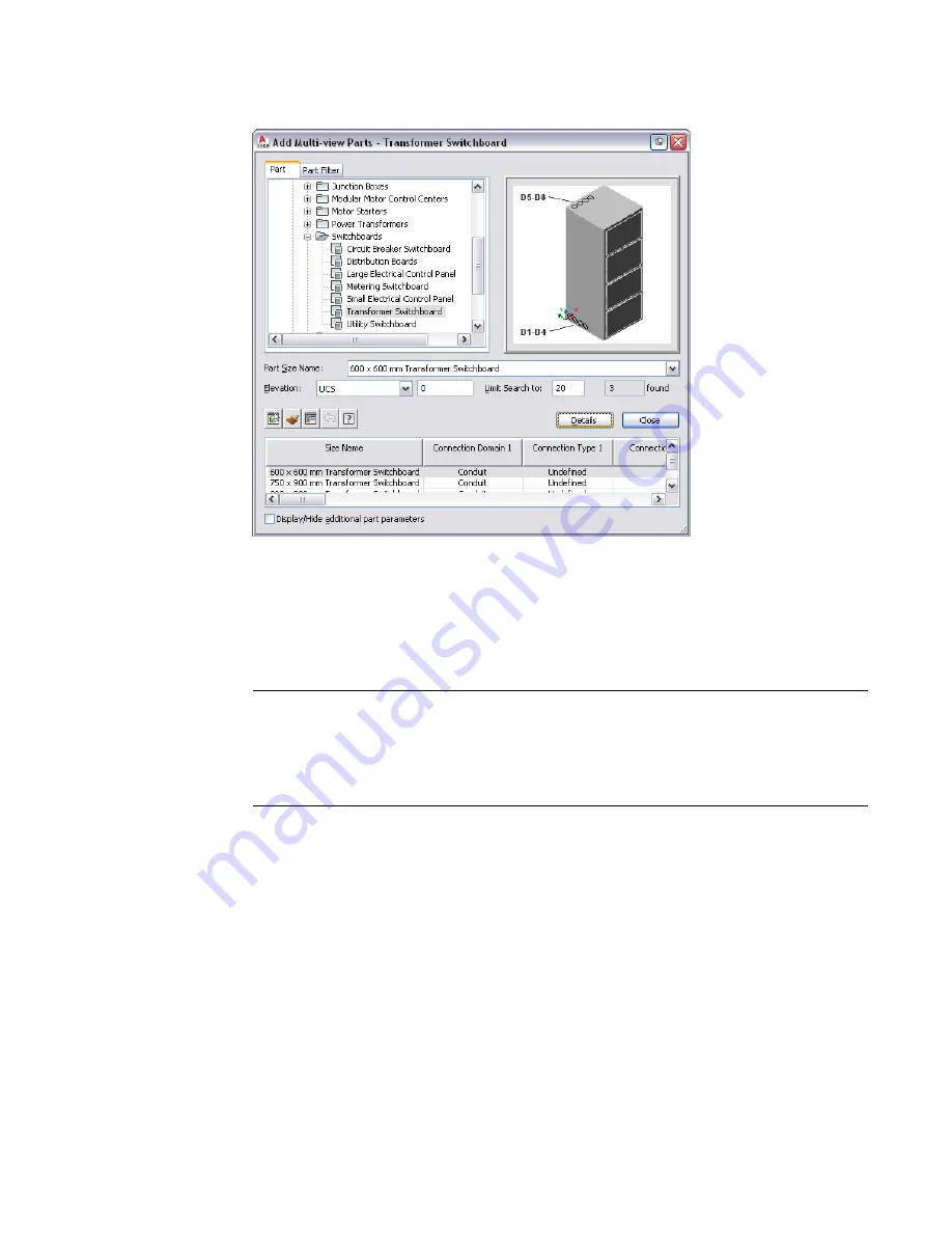
The software displays the Add Multi-view Parts dialog, which displays a tree view of the current
catalog.
The software opens the catalog at the part type folder associated with the tool you selected.
2
On the Part tab, select a part subtype in the part type folder.
3
Click Details to view the sizes available for the selected part subtype.
4
Some part types have large numbers of available sizes. If necessary, filter the list by clicking the
Part Filter tab and specifying the filtering criteria. For example, you can filter the list according
to connection size or type.
NOTE
The part catalogs and content locations specified in the Options dialog determine the parts
available to you when adding a part. For more information, see
on page 70.
If the part you want is not available, you or your CAD manager can create a custom part using
.
5
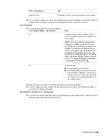
Select a part for Part Size Name.
6
Select a defined elevation from the list or enter a value for Elevation.
7
Specify an insertion point in the drawing, and use the compass to specify a rotation angle.
8
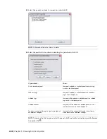
Repeat the preceding step to add additional parts with the same properties.
9
Press
Enter
to end the command.
Drawing Cable Trays and Conduits
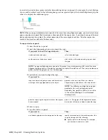
As you draw runs, the software inserts fittings, such as elbows and tees, to connect segments and runs to
other segments, runs, or equipment. The default parts specified in the cable tray and conduit preferences
420 | Chapter 9 Drawing Electrical Systems
Summary of Contents for 235B1-05A761-1301 - AutoCAD MEP 2010
Page 1: ...AutoCAD MEP 2010 User s Guide March 2009 ...
Page 22: ...4 ...
Page 86: ...68 ...
Page 146: ...128 ...
Page 180: ...162 ...
Page 242: ...Modifying the elevation of a duct 224 Chapter 6 Drawing HVAC Systems ...
Page 264: ...246 ...
Page 480: ...462 ...
Page 534: ...516 ...
Page 616: ...598 ...
Page 658: ...640 ...
Page 788: ...770 ...
Page 802: ...784 ...
Page 820: ...802 ...
Page 878: ...860 ...

