The plumbing module determines the total pressure drop for the run as follows:
Total Pressure Drop = Friction Loss + Elevation Change
4
Determine the available pressure for Friction Loss.
The plumbing module determines the pressure available for the Friction Loss by subtracting the
Pressure at Source from the Pressure at the Highest Fixture, minus Pressure Drop, minus Friction
Loss-Water Meter.
5
Compare the Pressure Drop to the Pressure Available.
The plumbing module then compares the Pressure Drop to the Pressure Available. These values
need to be equal to or greater than the available pressure. If the values do not match because
the pressure available is insufficient, then the plumbing module increases the size of the run by
one plumbing line size (all sizes go up one size) and recalculates the pressure drop.
6
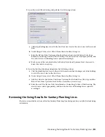
Display the results.
When the calculations are completed, the plumbing module displays the calculated values in
the Size Supply Plumbing Line dialog. For more information, see
on page 503.
Calculating the Sizes of Sanitary Plumbing Lines
Before you size a sanitary system, you should:
■
Complete a draft of the system.
■
Verify the accuracy of the fixture unit table you are using. For more information, see
on page 479.
■
Create a sizing table for sanitary plumbing lines based on applicable codes, such as the Uniform Plumbing
Code, or verify the accuracy of the table you are using. For more information, see
on page 480.
NOTE
You can only size sanitary plumbing systems whose system type is Waste.
Overview of Sizing Sanitary Plumbing Lines
You can only size sanitary systems whose system type is Waste. For example, if you create system definitions
for sanitary black water and sanitary gray water, you must define the system type as Waste. Otherwise, you
cannot size the systems. For information on creating system definitions, see
on page 477.
When you size a sanitary system, you can base the plumbing line sizing on 1 of 4 main types of runs:
■
Branch
■
Offset/Home Drains
■
Stack Spanning 3 Stories or Less
■
Stack Spanning More than 3 Stories
The type of run that you specify determines the sizing method that the software uses.
508 | Chapter 10 Drawing Plumbing Systems
Summary of Contents for 235B1-05A761-1301 - AutoCAD MEP 2010
Page 1: ...AutoCAD MEP 2010 User s Guide March 2009 ...
Page 22: ...4 ...
Page 86: ...68 ...
Page 146: ...128 ...
Page 180: ...162 ...
Page 242: ...Modifying the elevation of a duct 224 Chapter 6 Drawing HVAC Systems ...
Page 264: ...246 ...
Page 480: ...462 ...
Page 534: ...516 ...
Page 616: ...598 ...
Page 658: ...640 ...
Page 788: ...770 ...
Page 802: ...784 ...
Page 820: ...802 ...
Page 878: ...860 ...


