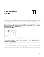
Schematic Lines
You can create schematic lines from AutoCAD
®
lines, arcs, or polylines.
In addition to assigning systems to schematic lines, you can create schematic line styles to distinguish
between different system types. Schematic line styles specify how crossing lines are displayed, the symbol
used to represent a connection point, and the list of available designation IDs, among other properties.
Schematic Symbols
AutoCAD MEP provides an extensive library of schematic symbols that snap together to represent the
connectivity and logical dependencies of real-world parts and equipment. Schematic symbols are style-based
content defined by a variety of style properties. Style properties specify the behavior of each schematic
symbol, such as how lines that connect to the symbol are trimmed. For more information, see
on page 603.
There are 2 types of schematic symbols:
■
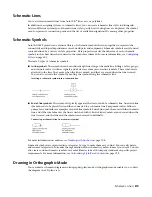
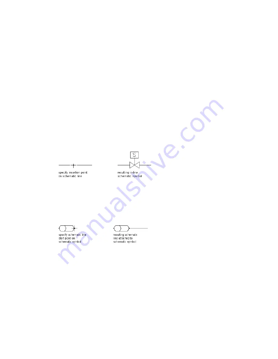
In-line symbols.
These symbols can be anchored anywhere along a schematic line. Fittings, valves, gauges,
and controls such as switches, signals, and devices are examples of in-line symbols. These symbols are
attached to the line. They move when the line is moved, and they are erased when the line is erased.
You can also relocate the symbol by moving the symbol along the schematic line.
Inserting a schematic symbol into a schematic line
■
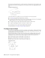
End-of-line symbols.
These symbols typically appear at the start or end of a schematic line. An end-of-line
symbol needs to be placed first and then connected to a schematic line. Equipment such as diffusers,
pumps, fans, and tanks are examples of end-of-line symbols. End-of-line symbols move with the schematic
line, and if the symbol moves the line is stretched with it. End-of-line symbols are not erased when the
line is erased, and the line and the symbol can be erased individually.
Connecting a schematic line to a schematic symbol
For more information on anchors, see
on page 108.
Schematic symbols are organized into categories by type to make them easy to find. You can add, delete,
and rename categories to customize the organization of the schematic symbols to meet your needs. You can
also create custom schematic symbols or symbol libraries to match company standards or specific project
requirements. For more information, see
Customizing Style-Based Content
on page 599.
Drawing in Orthographic Mode
You can draw a schematic diagram in orthographic (plan) mode. Orthographic mode enables you to draw
the diagram in a 2D plan view.
Schematic Lines | 519
Summary of Contents for 235B1-05A761-1301 - AutoCAD MEP 2010
Page 1: ...AutoCAD MEP 2010 User s Guide March 2009 ...
Page 22: ...4 ...
Page 86: ...68 ...
Page 146: ...128 ...
Page 180: ...162 ...
Page 242: ...Modifying the elevation of a duct 224 Chapter 6 Drawing HVAC Systems ...
Page 264: ...246 ...
Page 480: ...462 ...
Page 534: ...516 ...
Page 616: ...598 ...
Page 658: ...640 ...
Page 788: ...770 ...
Page 802: ...784 ...
Page 820: ...802 ...
Page 878: ...860 ...


