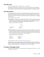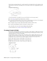
2
On the Properties palette, if necessary, specify or change the symbol to add by selecting a
schematic symbol style:
then…
If you want to select a schematic symbol
style…
expand Basic, and expand General. For Style, select the
style.
in the current drawing
on the General bar, click
. In the left pane of the Select
Schematic Symbol worksheet, navigate to the drawing that
in a drawing in the directory specified as the
default content location for schematic symbols
,
or in the style drawing referenced in the proper-
ties of a tool you selected
contains the style, and select the drawing. In the right pane,
select the style, and click OK.
3
For Description, click
, enter a description for the schematic symbol, and click OK.
4
For System, select the system to which the schematic symbol belongs.
You can select from the systems in the current drawing. For more information on systems, see
Creating Schematic System Definitions
on page 521.
5
If Orientation is enabled under Drawing Mode, select Ortho.
NOTE
If the style you selected does not have any defined isometric views, Orientation is read-only
and set to Ortho. For information on creating views for styles, see
page 604.
6
For Justification, select the point on the symbol to use as the insertion point.
You can select either the insertion point of the view block that represents the symbol, or one
of 9 other points on the device, such as Top Left or Middle Center.
7
Expand Advanced, and for ID, enter the ID to use to identify this symbol.
You can add the ID to your diagram
. The label style that you select when you add the
label determines the font and size of the ID.
8
In the drawing, click to specify the insertion point.
If you specify a point on a schematic line, the symbol breaks into and aligns with the line. It
then behaves like an
.
TIP
Use object snaps, such as Nearest or Midpoint, to help place schematic symbols.
9
Rotate the symbol into position, or enter the angle of rotation on the command line.
Alternatively, to accept the default rotation, press
ENTER
.
NOTE
The rotation is applied only to
. The rotation of an in-line symbol is
determined by the schematic line into which it is inserted.
10
Repeat the previous 2 steps to insert additional symbols with the same properties.
You can also modify the properties on the palette, and then add additional symbols.
11
Press
ENTER
to end the add command.
Adding Schematic Lines in Isometric Mode
, you add schematic lines on one of the 3 isometric planes: left,
top, or right. Each isometric plane has an associated pair of axes. Choosing an isometric plane causes the
528 | Chapter 11 Drawing Schematic Diagrams
Summary of Contents for 235B1-05A761-1301 - AutoCAD MEP 2010
Page 1: ...AutoCAD MEP 2010 User s Guide March 2009 ...
Page 22: ...4 ...
Page 86: ...68 ...
Page 146: ...128 ...
Page 180: ...162 ...
Page 242: ...Modifying the elevation of a duct 224 Chapter 6 Drawing HVAC Systems ...
Page 264: ...246 ...
Page 480: ...462 ...
Page 534: ...516 ...
Page 616: ...598 ...
Page 658: ...640 ...
Page 788: ...770 ...
Page 802: ...784 ...
Page 820: ...802 ...
Page 878: ...860 ...

