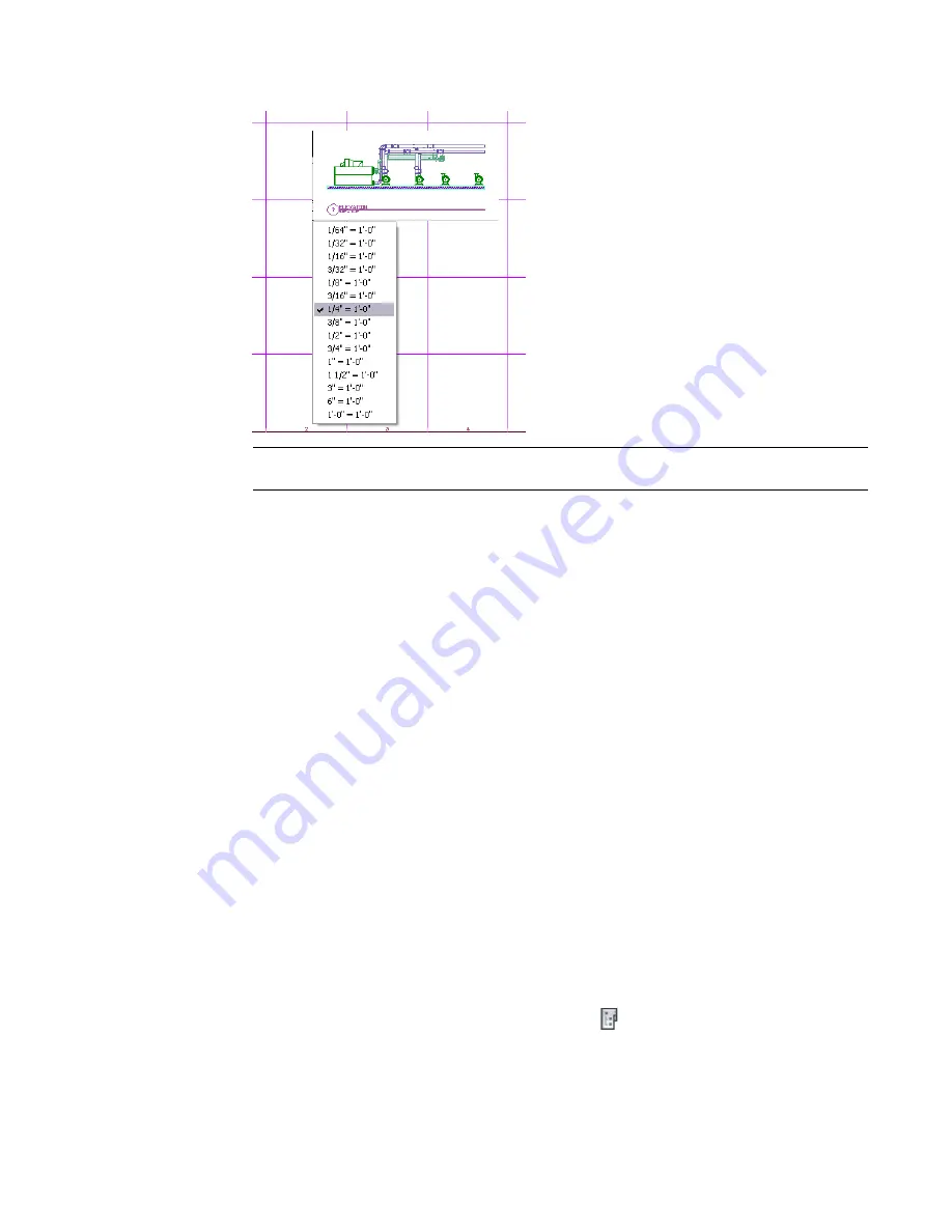
If you want to change the size of the view on the sheet, right-click and select a new scale.
NOTE
If you are placing a detail, section, or elevation view, only the specific view is added to the
sheet. The referenced plan view geometry is not displayed.
10
Specify the insertion point for the view.
11
To turn off grid marks in the viewport, double-click inside the viewport window.
12
Deselect Grid in the application status bar, then double-click outside the viewport window.
13
If desired, you can place more than one view on a sheet. You can also use a view on more than
one sheet.
The default sheet templates in the software include a layout grid to aid in locating views on a sheet. This
grid is not included in plots or DWF
™
output.
To move the viewport on the sheet, select the viewport boundary and use the basic modify tools in the
context menu. You can adjust the viewport size to change the viewable portion of the view drawing. You
can also activate the model space view by double-clicking inside the viewport. After you activate the model
space view, you can move or zoom the view drawing within the viewport. Double-click outside the viewport
to deactivate the model space view and return to paper space. In paper space, you cannot modify the drawing
within the viewport.
If you are placing detail, section, or elevation views on a sheet, the mark number and sheet number resolve
on both the source view drawing and model space view drawing. If you change the drawing name or directory
location for either view drawing, however, the mark and sheet number link will break. You may need to
recreate the mark to automatically resolve the number links.
Creating a Cover Sheet
You can create a cover sheet with a sheet list table that is dynamically linked to the drawings in the sheet
set. When you add the sheet list table, it automatically displays sheet names and numbers for all sheets in
the sheet set. If you add, reorder, or remove sheets from the set, you can update the sheet list table
automatically.
1
On the Quick Access Toolbar, click Project Navigator
.
2
On the Sheets tab of Project Navigator, create a new sheet as shown in
on page
576.
Sheets | 577
Summary of Contents for 235B1-05A761-1301 - AutoCAD MEP 2010
Page 1: ...AutoCAD MEP 2010 User s Guide March 2009 ...
Page 22: ...4 ...
Page 86: ...68 ...
Page 146: ...128 ...
Page 180: ...162 ...
Page 242: ...Modifying the elevation of a duct 224 Chapter 6 Drawing HVAC Systems ...
Page 264: ...246 ...
Page 480: ...462 ...
Page 534: ...516 ...
Page 616: ...598 ...
Page 658: ...640 ...
Page 788: ...770 ...
Page 802: ...784 ...
Page 820: ...802 ...
Page 878: ...860 ...


