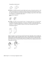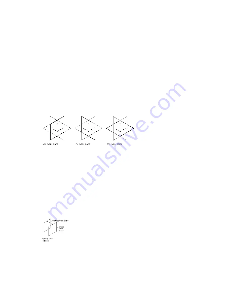
The following preset work planes can be added to a model from the Create Work Plane dialog:
Default
Creates the standard ZX, YZ, and XY work planes of the WCS.
Custom
Creates a work plane that is not available by the preset work planes. The work plane has user-defined
values for the X and Y direction and the origin of the plane in the current UCS.
Offset
Creates a work plane that is offset by a specified distance from a selected source work plane. For more
information, see
Offset and Reference Work Planes
on page 655.
Reference
Creates a work plane that is attached to the extents of a modifier feature. For more information,
Offset and Reference Work Planes
on page 655.
Top
Creates a work plane that matches the standard Top 3D view.
Bottom
Creates a work plane that matches the standard Bottom 3D view.
Front
Creates a work plane that matches the standard Front 3D view.
Back
Creates a work plane that matches the standard Back 3D view.
Left
Creates a work plane that matches the standard Left 3D view.
Right
Creates a work plane that matches the standard Right 3D view.
Viewing default work planes
Offset and Reference Work Planes
Offset and reference work planes are relational and are based on one or more defined features in the model,
such as other work planes or modifiers.
Offset Work Planes
An offset work plane is some distance away from another work plane. This work plane can be offset from
any existing work plane, including another offset or reference work plane. You define an offset work plane
by selecting a source work plane and specifying a distance between the work planes. You can use offset work
planes to maintain specified or calculated distances between features, such as profiles, geometry, or modifiers.
You can also use offset work planes as construction guides for locating features that would otherwise be
difficult to locate parametrically. For example, use an offset work plane to define the length of a transition.
Creating an offset work plane
Reference Work Planes
A reference work plane is defined as a plane on the face of the extents of a modifier. Every modifier has an
invisible extent, or boundary box, that defines the extents of the feature. You can create a work plane that
Building Parametric Fittings Using Content Builder | 655
Summary of Contents for 235B1-05A761-1301 - AutoCAD MEP 2010
Page 1: ...AutoCAD MEP 2010 User s Guide March 2009 ...
Page 22: ...4 ...
Page 86: ...68 ...
Page 146: ...128 ...
Page 180: ...162 ...
Page 242: ...Modifying the elevation of a duct 224 Chapter 6 Drawing HVAC Systems ...
Page 264: ...246 ...
Page 480: ...462 ...
Page 534: ...516 ...
Page 616: ...598 ...
Page 658: ...640 ...
Page 788: ...770 ...
Page 802: ...784 ...
Page 820: ...802 ...
Page 878: ...860 ...

