Point Reference
Defined by a point in the work plane that is based on a source point selected from a different
work plane. A point reference is moved or deleted with the source point.
Project Geometry
Defined by a projection of a modifier on a specified work plane. The project geometry is
fixed and cannot be moved in the work plane. It is linked to the modifier and adjusts as the modifier changes.
Dimensions
Models require dimension information to maintain size and position for the design. Dimensions are typically
added after you have finalized the geometric features of the model or when placing a connector; however,
you can add dimensions at any time during the creation process. When you add dimensions, you apply
rules that control the size and position of features in the model. Dimensions work in conjunction with
constraints. The model is updated when changes are made to the dimensions.
Dimensions specify the length, diameter, or rotation angle of geometric elements in the model. When a
dimension is added, a corresponding size parameter is also added. This parameter creates a placeholder value
for the dimension that provides flexibility for defining the values of dimensions. Dimensions can be defined
as default numeric constants or as equations. Although you can use them interchangeably, they each have
specific uses.
■
Numeric constants are useful when a geometric element has a static or fixed size that is populated as a
value in a basic table, list, or constant storage type.
■
Equations are useful when the size of a feature icon must be mathematically defined relative to the size
of another feature.
Content Builder assigns a variable name to each dimension parameter. Letters and numbers are used to
signify the type of dimension (such as length or diameter) and the sequence in which the dimension was
added to the model (1 for first, 2 for second, and so on). To keep the model shape from becoming distorted
as the dimensions resize it, define the large dimensions first. Dimension type depends on the feature you
choose and where you place the dimensions.
NOTE
When adding dimensions it is recommended to select points to specify the start and end locations. It is
also helpful to turn off geometry that you are not dimensioning for ease of selection.
Viewing dimension types
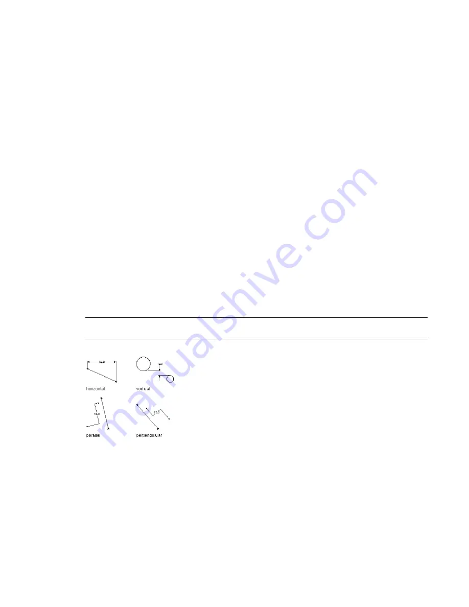
Content Builder provides 7 types of dimensions you can add to the model:
Distance
Can be defined for pairs of geometry of all types. Defines a value between 2 features. The value of
a distance dimension cannot be negative. When adding distance dimensions between 2 lines, it is implied
that the lines are parallel with a given separation.
Horizontal Distance
Can be defined for pairs of geometry of all types. Defines a value between 2 features
in a horizontal direction. The value of a distance dimension cannot be negative.
Vertical Distance
Can be defined for pairs of geometry of all types. Defines a value between 2 features in a
vertical direction. The value of a distance dimension cannot be negative.
Building Parametric Fittings Using Content Builder | 657
Summary of Contents for 235B1-05A761-1301 - AutoCAD MEP 2010
Page 1: ...AutoCAD MEP 2010 User s Guide March 2009 ...
Page 22: ...4 ...
Page 86: ...68 ...
Page 146: ...128 ...
Page 180: ...162 ...
Page 242: ...Modifying the elevation of a duct 224 Chapter 6 Drawing HVAC Systems ...
Page 264: ...246 ...
Page 480: ...462 ...
Page 534: ...516 ...
Page 616: ...598 ...
Page 658: ...640 ...
Page 788: ...770 ...
Page 802: ...784 ...
Page 820: ...802 ...
Page 878: ...860 ...


