3
Click Default, and click OK.
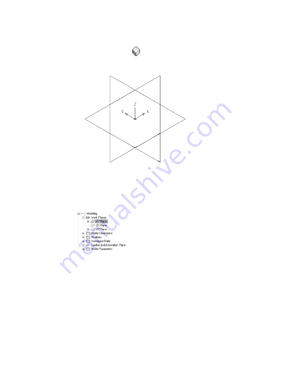
The ZX plane, YZ plane, and XY plane are created.
4
To view the work planes in the modeling area, on the floating View panel, click View
drop-down
➤
SW Isometric
.
5
In the part browser, expand Work Planes.
When you select a work plane in the part browser, the work plane is highlighted in the modeling
area.
Selecting the ZX Plane
6
To avoid confusion, work with only one work plane visible at a time. In the part browser,
right-click ZX Plane and click Visible. Do the same for XY Plane.
The ZX Plane and XY Plane icons are unavailable (shaded). The YZ plane is the only visible work
plane in the modeling area.
Modeling the Trunk of a Parametric Tee Fitting
Use this procedure to model the trunk of the tee fitting. You add the circular
on page 656, create
the profile, and apply an extrusion modifier.
1
To create the trunk of the tee, in the part browser, right-click YZ Plane and click Add
Profile
➤
Circular.
678 | Chapter 14 Customizing Catalog-Based Content
Summary of Contents for 235B1-05A761-1301 - AutoCAD MEP 2010
Page 1: ...AutoCAD MEP 2010 User s Guide March 2009 ...
Page 22: ...4 ...
Page 86: ...68 ...
Page 146: ...128 ...
Page 180: ...162 ...
Page 242: ...Modifying the elevation of a duct 224 Chapter 6 Drawing HVAC Systems ...
Page 264: ...246 ...
Page 480: ...462 ...
Page 534: ...516 ...
Page 616: ...598 ...
Page 658: ...640 ...
Page 788: ...770 ...
Page 802: ...784 ...
Page 820: ...802 ...
Page 878: ...860 ...


