7
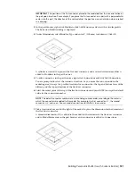
Select a different view from the list, or click
to view the model using 3D orbit navigation.
8
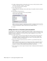
In the Parametric Object Viewer, select a point on the circle, and drag the cursor along the
circumference of the circle to inspect the 3D model dynamically from various viewpoints.
9
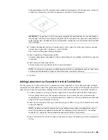
With the Parametric Object Viewer open, select a different part size in the Size Parameters dialog.
The part size is displayed in the viewer.
10
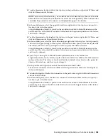
Inspect the model from various viewpoints to verify that the model appears sound.
If your inspection reveals problems, such as segments that join improperly, make the necessary
modifications, and inspect the part sizes again. Repeating this process until all part sizes appear
sound.
11
Click
to close the Parametric Object Viewer.
Creating a Schematic Symbol of a Parametric MvPart
You can create a schematic symbol for a parametric MvPart at any time. However, only parts that you add
to drawings after you have created the symbol can use the symbol. You cannot update previously inserted
parts to use the symbol.
There are 2 types of schematic symbols that you can add to parametric MvParts:
■
Parametric.
This type of symbol scales proportionally with the part. You create parametric symbols using
parametric features: parametric geometry, dimensions, and constraints.
■
Block-based.
This type of symbol scales uniformly instead of proportionally. You create block-based
symbols using standard AutoCAD
®
objects, such as lines, arc, and circles. You can create the symbol
from scratch, or you can insert an existing AutoCAD MEP symbol or 2D AutoCAD block from a DWG
file. This allows you to take advantage of existing symbol libraries or block libraries.
Creating a Parametric Symbol
1
If necessary, open the parametric MvPart in Content Builder.
2
In the part browser, right-click
, and click Visible.
NOTE
Although this step makes the plane visible in the drawing area, its position on the Z axis in
the World Coordinate System (WCS) is high above the WCS origin, so you might need to zoom out
to view the plane. You can also
3
Right-click Symbol and Annotation Plane, and click Set View.
This changes the view direction to Top (plan) view, which is the default view for the plane as
well as the most common view for drawing schematic symbols. However, you can select any
view that is helpful for drawing the geometry.
4
Create the schematic symbol using parametric
, and
.
First, use the model geometry that changes with part size to create point references and projected
geometry on the Symbol and Annotation plane. Next, create the symbol geometry on the plane.
Finally, add constraints and/or dimensions so that the symbol changes accordingly when the
part size changes.
To access the necessary commands, expand Symbol and Annotation Plane, right-click Parametric
Graphics, and use the commands on the context menu, as follows. Click Add Geometry, and
then click Point Reference.
Building Parametric MvParts with Content Builder | 735
Summary of Contents for 235B1-05A761-1301 - AutoCAD MEP 2010
Page 1: ...AutoCAD MEP 2010 User s Guide March 2009 ...
Page 22: ...4 ...
Page 86: ...68 ...
Page 146: ...128 ...
Page 180: ...162 ...
Page 242: ...Modifying the elevation of a duct 224 Chapter 6 Drawing HVAC Systems ...
Page 264: ...246 ...
Page 480: ...462 ...
Page 534: ...516 ...
Page 616: ...598 ...
Page 658: ...640 ...
Page 788: ...770 ...
Page 802: ...784 ...
Page 820: ...802 ...
Page 878: ...860 ...

