Adding Annotation to a Schematic Symbol
You can add annotation to the schematic symbol of a parametric MvPart regardless of whether the symbol
is
. To add the annotation, you create a multiline text (mtext) object, which the
software then uses to create the text block to associate with the symbol.
When the symbol is inserted into a drawing, the text block is inserted as well. If the symbol changes in size,
the text block is repositioned to maintain the same relative position.
To add annotation to a parametric or block-based schematic symbol
1
If necessary, open the MvPart in Content Builder.
2
In the part browser, expand Modeling, and expand Symbol and Annotation Plane.
3
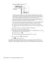
Right-click Annotation Text, and click Add Annotation Text.
4
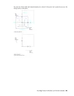
In the drawing area, specify opposite corners of a bounding box to define the width of the
multiline text object.
5
Use the In-Place Text Editor to enter the annotation text and specify its properties, such as the
character height expressed in terms of the drawing units.
For information on using the In-Place Text Editor, see “Overview of Multiline Text” in AutoCAD
Help.
TIP
If you set the character height of the annotation text in your building systems drawings to 1 unit,
you can control the plot size of annotation entirely by the Annotation Plot Size setting on the Scale
tab of the Drawing Setup dialog. For example, if the units for a drawing are inches, and the annotation
plot size for the drawing is 3/32”, then setting the annotation text in the drawing to 1” results in a
text height of 3/32” for the plotted annotation.
6
Save your changes, and exit the editor by doing one of the following:
■
Click in the drawing outside the editor.
■
Click OK on the toolbar.
■
Press
CTRL
+
ENTER
.
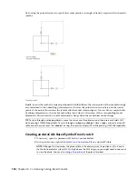
The software creates the text block and attaches it to the Symbol and Annotation plane. The
text block now appears in the part browser under Annotation Text.
7
If you want the annotation text to remain horizontal regardless of the rotation angle of the part
when it is inserted, select the text block, right-click, and click Keep Text Horizontal.
To delete the annotation text block, you can select the block in the drawing area, and press
DELETE
.
Modifying Parametric Parts Using Content Builder
You can modify existing parametric parts with Content Builder. For parts in the catalogs provided by AutoCAD
MEP, you can change the part behavior, part size parameters, and connectors. For parametric parts you create
using Content Builder, you can change the part behaviors, part size parameters, connectors, and part model
including geometry, profiles, modifiers, constraints, and dimensions. You can also delete parts that you no
longer need. Deleting parts can be helpful when creating custom catalogs to ensure that all associated
definition files are managed correctly.
Starting Content Builder for Modifying a Parametric Part
Use this procedure to start Content Builder and open the parametric building environment for modifying
a parametric part.
Modifying Parametric Parts Using Content Builder | 741
Summary of Contents for 235B1-05A761-1301 - AutoCAD MEP 2010
Page 1: ...AutoCAD MEP 2010 User s Guide March 2009 ...
Page 22: ...4 ...
Page 86: ...68 ...
Page 146: ...128 ...
Page 180: ...162 ...
Page 242: ...Modifying the elevation of a duct 224 Chapter 6 Drawing HVAC Systems ...
Page 264: ...246 ...
Page 480: ...462 ...
Page 534: ...516 ...
Page 616: ...598 ...
Page 658: ...640 ...
Page 788: ...770 ...
Page 802: ...784 ...
Page 820: ...802 ...
Page 878: ...860 ...

