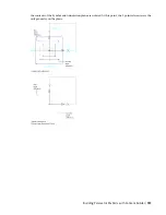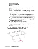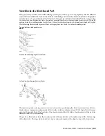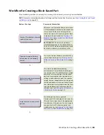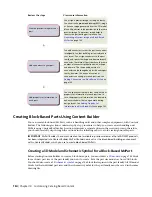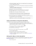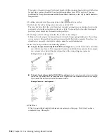
with the top-view insertion point offset by the height of the air handling unit. The front and back views
have an insertion point at the right corner of the bottom edge, with the back-view insertion point offset by
the width of the air handling unit. The left and right views have an insertion point at the bottom-front
corner, with the left-view insertion point offset by the length of the air handling unit.
Once view blocks are generated, they are assigned to the appropriate display representation based on view
direction, name, and view block. You can change the default assignments as needed. It is possible to assign
the same view block to multiple view directions, such as front and back, depending on the part symmetry.
The view block assignments are as follows:
View Direction
Display Representation
View Block
Top
1 Line
Top
Top
2 Line
Bottom
1 Line
Bottom
Bottom
2 Line
Front
1 Line
Front
Front
2 Line
Back
1 Line
Back
Back
2 Line
Left
1 Line
Left
Left
2 Line
Right
1 Line
Right
Right
2 Line
3D
1 Line
Model
3D
2 Line
All directions
Model
All directions
Schematic
Symbol
NOTE
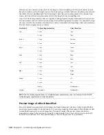
The Plan display representation is a standard display representation and is not used by AutoCAD MEP.
Standard display representations cannot be deleted.
Preview Image of a Block-Based Part
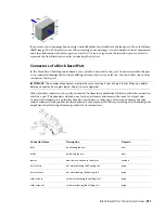
Every part family has a graphical preview image that helps during part selection. Using Content Builder,
you assign a preview image to the part family. You can create an image before using Content Builder or have
Content Builder generate a preview image based on the 3D model. The preview image should be a
representative image of the part family, typically a shaded model view of one of the part sizes in the SW
isometric view direction. The same preview image is used for all part sizes of a part family.
750 | Chapter 14 Customizing Catalog-Based Content
Summary of Contents for 235B1-05A761-1301 - AutoCAD MEP 2010
Page 1: ...AutoCAD MEP 2010 User s Guide March 2009 ...
Page 22: ...4 ...
Page 86: ...68 ...
Page 146: ...128 ...
Page 180: ...162 ...
Page 242: ...Modifying the elevation of a duct 224 Chapter 6 Drawing HVAC Systems ...
Page 264: ...246 ...
Page 480: ...462 ...
Page 534: ...516 ...
Page 616: ...598 ...
Page 658: ...640 ...
Page 788: ...770 ...
Page 802: ...784 ...
Page 820: ...802 ...
Page 878: ...860 ...

