TIP
Name the symbol block “symbol” to have Content Builder by default use the symbol block as
the source for generating the 3D symbol.
5
Under Objects, click the Select Objects option, and then select the geometry that will make up
the symbol block.
The dialog closes temporarily while you select objects for the symbol block. Press
ENTER
when
you finish selecting objects. The dialog reopens.
6
Under Objects, select one of the following options:
■
Retain.
Keeps selected objects in the current drawing in their original state.
■
Convert to Block.
Replaces selected objects with an instance of the block.
■
Delete.
Removes selected objects after the block is defined.
7
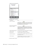
Under Base Point, click the Pick Point option and select the block insertion point.
The insertion point, or base point, is used as a reference for positioning the block.
8
Under Description, enter text to help identify the symbol block for easy retrieval.
9
To attach a hyperlink to the part, click Hyperlink, select a file or web page, and click OK twice.
The symbol block is saved in the current drawing.
RELATED
For more information, see “Block Definition Dialog Box” in the AutoCAD Help.
Starting Content Builder for Creating a Block-Based MvPart
Use this procedure to start Content Builder and open the block-based building environment.
1
Open the drawing file that contains the 3D model block(s) of the part you want to create.
Each part size requires a unique 3D model block. You can have one or more model blocks in a
single drawing file that represent each part size in a part family.
2
Click Manage tab
➤
MEP Content panel
➤
Content Builder
.
The Getting Started - Catalog Screen dialog is displayed.
3
Select Multi-view Part for Part Domain.
4
In the tree view, select a chapter to add the new MvPart to, and click
.
The New Part dialog is displayed.
5
Enter a name and description for the part family, and click OK.
By default, the description is the same as the name until you change it.
The block-based building environment is opened. For more information, see
on page 643.
Defining the Part Behavior of a Block-Based MvPart
Use this procedure to define the part behavior of a block-based MvPart by specifying the type, subtype, layer
key, and method of insertion for all part sizes of the MvPart. For more information, see
on page 747.
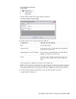
1
Select a type from the list.
Creating Block-Based Parts Using Content Builder | 757
Summary of Contents for 235B1-05A761-1301 - AutoCAD MEP 2010
Page 1: ...AutoCAD MEP 2010 User s Guide March 2009 ...
Page 22: ...4 ...
Page 86: ...68 ...
Page 146: ...128 ...
Page 180: ...162 ...
Page 242: ...Modifying the elevation of a duct 224 Chapter 6 Drawing HVAC Systems ...
Page 264: ...246 ...
Page 480: ...462 ...
Page 534: ...516 ...
Page 616: ...598 ...
Page 658: ...640 ...
Page 788: ...770 ...
Page 802: ...784 ...
Page 820: ...802 ...
Page 878: ...860 ...

