3
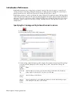
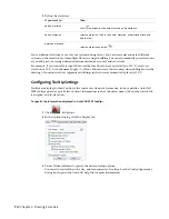
Define the elevation:
then…
If you want to…
click
and specify the name, elevation, and description.
add an elevation
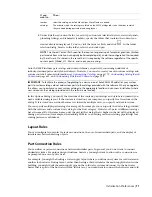
select an elevation. Click in the name, elevation, or description field and
edit the text.
edit an elevation
select an elevation and click
.
delete an elevation
You can define elevations to use for your systems during layout. You can create elevations for different
systems on the same floor or for multiple floors in a single building. You can also manually enter elevations
as you add parts, but using defined elevations maintains accuracy and saves time.
For example, if you want all air supply ducts on the first floor to have an elevation of 12'-0'', create an
elevation of 12'-0'' with the name Supply - 1st Floor. You can select this elevation when adding duct in the
drawing. All non-vertical duct segments and fittings in the run are automatically placed at 12'-0''.
Configuring Tooltip Settings
Tooltips are displayed when you hover the cursor over items such as menus, icons or palettes. AutoCAD
MEP tooltips provide a quick view of object information, such as the object name, the system to which it
is assigned, and its elevation.
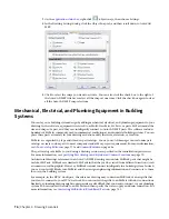
To specify the information displayed in AutoCAD MEP tooltips
1
Click
➤
Options.
2
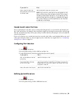
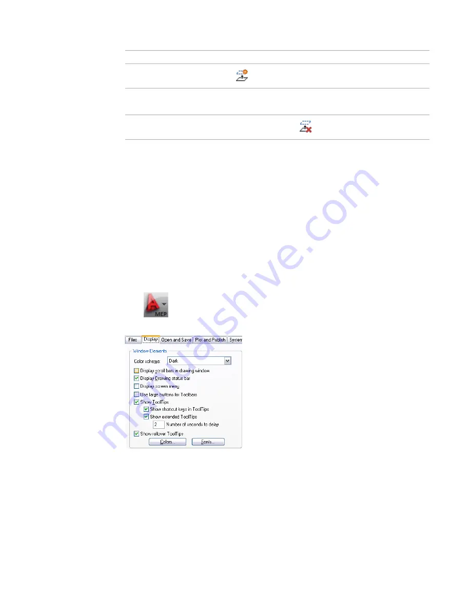
In the Options dialog, click the Display tab.
3
Under Window Elements, specify the desired tooltip options.
You can also control the color, size, and transparency of tooltips. See the Tooltip Appearance
Dialog Box topic in the AutoCAD help file for more information.
74 | Chapter 4 Drawing Essentials
Summary of Contents for 235B1-05A761-1301 - AutoCAD MEP 2010
Page 1: ...AutoCAD MEP 2010 User s Guide March 2009 ...
Page 22: ...4 ...
Page 86: ...68 ...
Page 146: ...128 ...
Page 180: ...162 ...
Page 242: ...Modifying the elevation of a duct 224 Chapter 6 Drawing HVAC Systems ...
Page 264: ...246 ...
Page 480: ...462 ...
Page 534: ...516 ...
Page 616: ...598 ...
Page 658: ...640 ...
Page 788: ...770 ...
Page 802: ...784 ...
Page 820: ...802 ...
Page 878: ...860 ...

