Part (.ipt) Files
When you open a part file, you are in the part environment. Part tools
manipulate sketches, features, and bodies which combine to make parts. You
can insert a single body part into assemblies and constrain them in positions
they occupy when the assembly is manufactured. You can extract multiple
part files from a multi-body part.
Most parts start with a sketch. A sketch is the profile of a feature and any
geometry (such as a sweep path or axis of rotation) required to create the
feature.
A part model is a collection of features. If necessary, solid bodies in a
multi-body part file can share features. Sketch constraints control geometric
relationships such as parallel and perpendicular. Dimensions control the size.
Collectively this method is called Parametric modeling. You can adjust the
constraints or dimensional parameters that control the size and shape of a
model, and automatically see the effect of your modifications.
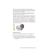
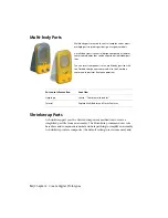
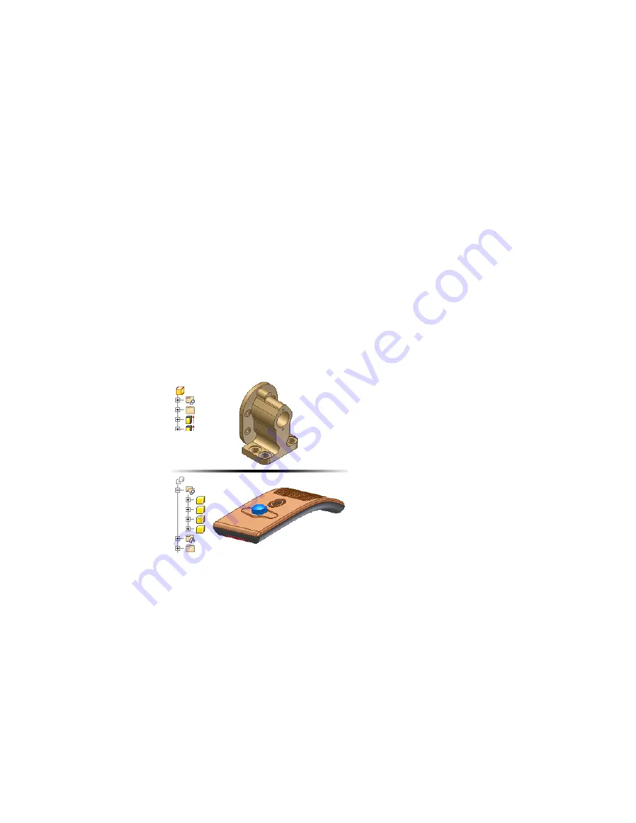
The following image shows a single body part in the upper half of the image,
and a multi-body part in the lower half of the image. Notice the different part
icons in each image.
Assembly (.iam) Files
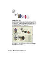
In Autodesk Inventor, you place components that act as a single functional
unit into an assembly document. Assembly constraints define the relative
position these components occupy with respect to each other. An example is
the axis of a shaft aligning with a hole in a different component.
4 | Chapter 1 Digital Prototypes in Autodesk Inventor
Summary of Contents for 466B1-05A761-1304 - AutoCAD Inventor Simulation Suite 2010
Page 1: ...Autodesk Inventor 2010 Getting Started January 2009 Part No 527B1 050000 PM01A ...
Page 6: ...vi ...
Page 60: ...54 ...
Page 80: ...74 ...


