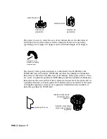
Real and Photo Raytrace renderers provide default mapping, but this doesn’t
always give the results you want.
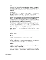
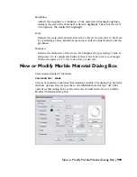
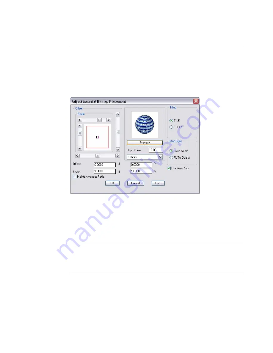
Adjust Material Bitmap Placement Dialog Box
View menu: Render
➤
Materials
Command line:
rmat
Adjusts how the material bitmap is placed on the objects.
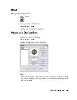
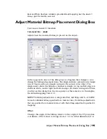
In the upper-left corner of the dialog box is a diagram that changes as you
change the bitmap placement values. The diagram shows a projection rectangle
in red. The projection rectangle represents the extents of an object. The
diagram also shows the bitmap as another rectangle: its top and left edges are
drawn in white, and its right and bottom edges are drawn in magenta. When
you first see this dialog box, the two squares are the same size. As this implies,
the default mapping scale is 1:1.
NOTE
The bitmap adjustment—scaling and offset, and tiling switch—can differ
for each individual bitmap specified for a material. Also, the bitmap adjustments
that are specified for a material interact with the bitmap adjustment specified in
mapping.
Offset
Changes the origin of the bitmap relative to the origin of the UV projection
coordinates. Offset values can range from –1 to 1 in either dimension (U or
Adjust Material Bitmap Placement Dialog Box | 995
Summary of Contents for AUTOCAD 2006
Page 1: ...February 2005 AutoCAD 2006 Command Reference ...
Page 24: ......
Page 30: ...6 ...
Page 212: ...188 ...
Page 448: ...424 ...
Page 554: ...530 ...
Page 584: ...560 ...
Page 588: ...564 ...
Page 660: ...636 ...
Page 750: ...726 ...
Page 760: ...736 ...
Page 960: ...936 ...
Page 1194: ...1170 ...
Page 1244: ...Undo Reverses the most recent change made by TRIM 1220 Chapter 21 ...
Page 1310: ...1286 ...
Page 1328: ...1304 ...
Page 1354: ...Zoom Window Zooms to display an area specified by a rectangular window 1330 Chapter 26 ...
Page 1490: ......

