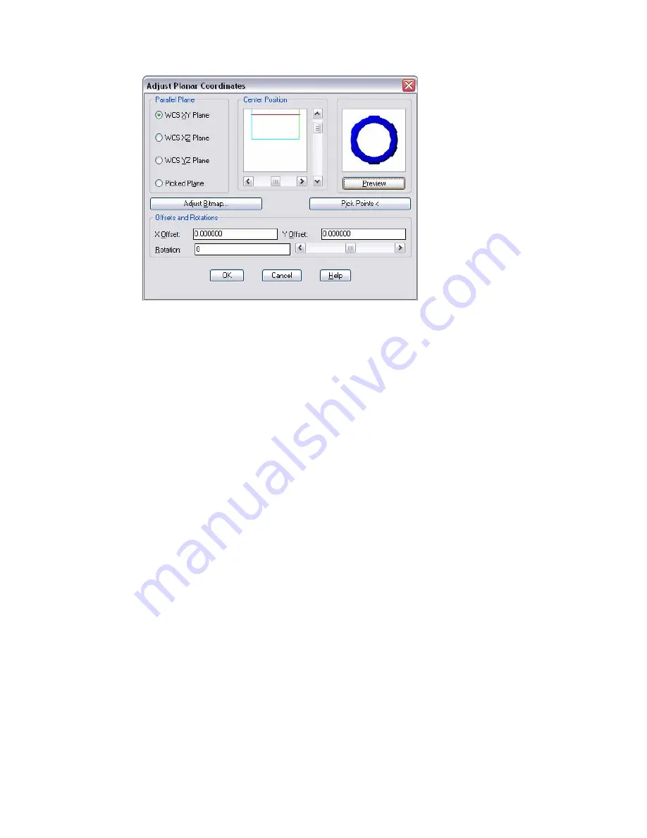
Adjust Bitmap
Displays the Adjust Object Bitmap Placement Dialog Box, in which you can
adjust the bitmap’s offset and scaling.
Center Position
Shows a parallel projection of the object’s mesh onto the current parallel
plane. It also shows the current projection square in blue (the top of the
projection square is indicated by a small blue tick mark, and the square’s
left edge is shown in green). You can move the projection square by moving
the scroll bars.
By default, the projection square is the smallest square that can be drawn
around the parallel projection of the object’s bounding box (its extents).
Offsets and Rotations
Changes the X and Y offsets of the map. You can change the rotation by
using the scroll bar or entering a new value.
Parallel Plane
Specifies one of the three perpendicular reference planes of the world
coordinate system (WCS) or a plane you specify by clicking Pick Points. If
you select Picked Plane and then click OK without clicking Pick Points, the
XY plane of the WCS is used by default.
You must set the appropriate WCS plane when using fixed-scale materials
on objects using object mapping coordinates to ensure that the bitmap
placement scale, offset, and rotation work in the correct plane regardless
of the UCS.
1056 | Chapter 20
Summary of Contents for AUTOCAD 2006
Page 1: ...February 2005 AutoCAD 2006 Command Reference ...
Page 24: ......
Page 30: ...6 ...
Page 212: ...188 ...
Page 448: ...424 ...
Page 554: ...530 ...
Page 584: ...560 ...
Page 588: ...564 ...
Page 660: ...636 ...
Page 750: ...726 ...
Page 760: ...736 ...
Page 960: ...936 ...
Page 1194: ...1170 ...
Page 1244: ...Undo Reverses the most recent change made by TRIM 1220 Chapter 21 ...
Page 1310: ...1286 ...
Page 1328: ...1304 ...
Page 1354: ...Zoom Window Zooms to display an area specified by a rectangular window 1330 Chapter 26 ...
Page 1490: ......


