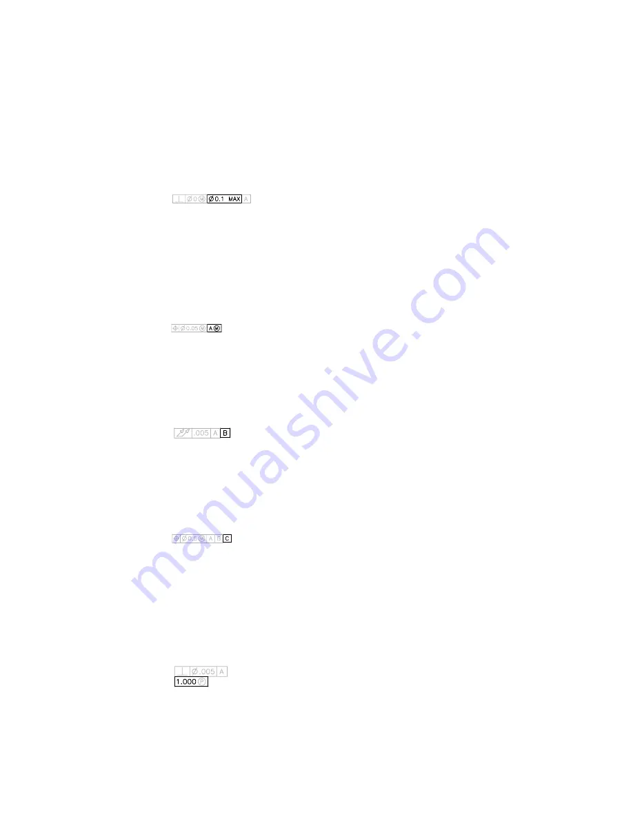
Select the symbol you want to use. The dialog box closes. The symbol is
inserted into the MC box for the first tolerance value in the Geometric
Tolerance dialog box.
Tolerance 2
Creates the second tolerance value in the feature control frame. Specify the
second tolerance value in the same way as the first.
Datum 1
Creates the primary datum reference in the feature control frame. The datum
reference can consist of a value and a modifying symbol. A datum is a
theoretically exact geometric reference used to establish the tolerance zone
for a feature.
Datum 2
Creates the secondary datum reference in the feature control frame in the
same way as the primary datum reference.
Datum 3
Creates the tertiary datum reference in the feature control frame in the same
way as the primary datum reference.
Height
Creates a projected tolerance zone value in the feature control frame. A
projected tolerance zone controls the variation in height of the extended
portion of a fixed perpendicular part and refines the tolerance to that specified
by positional tolerances. Enter a value in the box.
Geometric Tolerance Dialog Box | 1201
Summary of Contents for AUTOCAD 2006
Page 1: ...February 2005 AutoCAD 2006 Command Reference ...
Page 24: ......
Page 30: ...6 ...
Page 212: ...188 ...
Page 448: ...424 ...
Page 554: ...530 ...
Page 584: ...560 ...
Page 588: ...564 ...
Page 660: ...636 ...
Page 750: ...726 ...
Page 760: ...736 ...
Page 960: ...936 ...
Page 1194: ...1170 ...
Page 1244: ...Undo Reverses the most recent change made by TRIM 1220 Chapter 21 ...
Page 1310: ...1286 ...
Page 1328: ...1304 ...
Page 1354: ...Zoom Window Zooms to display an area specified by a rectangular window 1330 Chapter 26 ...
Page 1490: ......


