You can use the Node object snap to draw an object by snapping to the point
objects. You can then remove the points by entering
erase previous
.
The markers are placed in the user coordinate system (UCS) of the object being
measured (except for 3D polylines in the current UCS). Markers are always
placed on the object, regardless of the elevation settings.
If you use point objects for the markers, you can make the points easier to see
by changing their appearance with the PDMODE system variable.
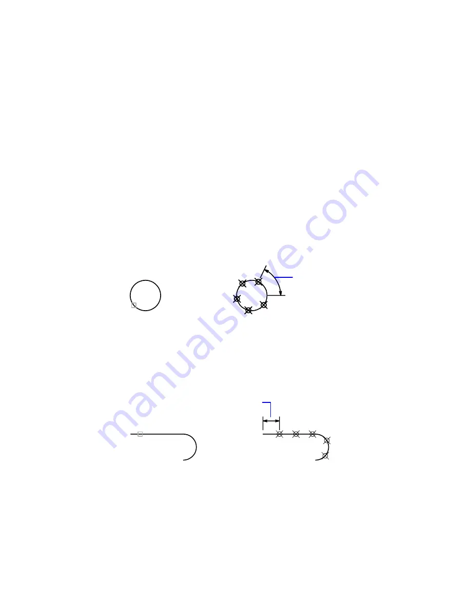
Length of Segment
Places point objects at the specified interval along the selected object,
starting at the endpoint closest to the point you used to select the object.
Measurement of closed polylines starts at their initial vertex (the first one
drawn).
Measurement of circles starts at the angle from the center set as the current
snap rotation angle. If the snap rotation angle is 0, then the measurement
of the circle starts to the right of center, on its circumference.
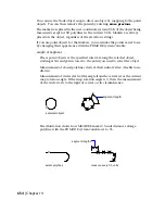
selected object
segment length
The illustration shows how MEASURE marks 0.5-unit distances along a
polyline, with the PDMODE system variable set to 35.
select polylines
measure every 0.5 units
segment lengths
654 | Chapter 14
Summary of Contents for AUTOCAD 2006
Page 1: ...February 2005 AutoCAD 2006 Command Reference ...
Page 24: ......
Page 30: ...6 ...
Page 212: ...188 ...
Page 448: ...424 ...
Page 554: ...530 ...
Page 584: ...560 ...
Page 588: ...564 ...
Page 660: ...636 ...
Page 750: ...726 ...
Page 760: ...736 ...
Page 960: ...936 ...
Page 1194: ...1170 ...
Page 1244: ...Undo Reverses the most recent change made by TRIM 1220 Chapter 21 ...
Page 1310: ...1286 ...
Page 1328: ...1304 ...
Page 1354: ...Zoom Window Zooms to display an area specified by a rectangular window 1330 Chapter 26 ...
Page 1490: ......


