Strona
27
z
34
2.15.
3D
multiplier
calibration
map
“digital”
(for
STAG
‐
300
Plus,
STAG
‐
300
Premium
controller
only)
Upon
pressing
the
“RPM
calibration”
tab,
a
digital
multiplier
calibration
map
is
displayed
in
the
map
window.
This
map
is
a
different
method
of
visualising
the
3D
map
described
in
2.11.
The
digital
map
offers
new
possibilities
presented
below.
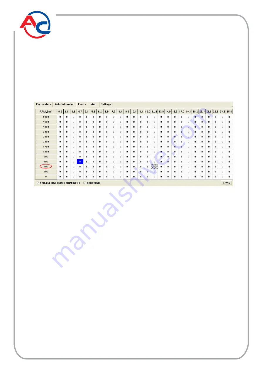
Fig.
19
“Digital”
multiplier
calibration
map
view.
Thanks
to
the
“digital”
multiplier
calibration
map
shown
above,
it
is
possible
to
modify
the
multiplier
according
to
rpm
in
the
same
manner
as
in
the
case
of
a
“graphic”
3D
map,
also
as
regards
the
method
of
operating
it
by
means
of
a
keyboard.
All
changes
to
the
“graphic”
map
will
be
represented
in
the
“digital”
map
and
vice
versa
because
physically
there
is
only
one
map
in
the
controller
memory,
only
the
method
of
presentation
is
different.
A
far
as
map
modifications
are
concerned,
the
following
additional
options
are
also
available:
“Changing
value
change
neighbour
too”
–
(if
selected)
in
the
case
of
modifying
the
selected
area,
the
neighbouring
fields
are
modified
as
well.
“Show
values”
–
(if
selected)
the
controller
displays
calibration
values
in
per
cent.
In
this
display
mode,
the
“Erase”
button
can
be
seen.
By
pressing
this
button,
all
map
settings
can
be
deleted
(the
map
can
be
reset).
The
vertical
axis
shows
rpm
values
for
individual
intervals
on
the
map.
The
red
border
marks
the
boundary
between
the
first
and
the
second
rpm
interval.
If
intervals
are
set
as
presented
in
the
second
interval
operates
from
300
to
500
rpm,
while
the
third
interval
operates
from
500
to
600
rpm.
The
boundaries
between
individual
intervals
can
be
regulated
by
clicking
on
the
correct
field
and
entering
a
new
interval
boundary
value.
Thanks
to
this
option,
it
is
possible
to
adjust
the
mixture
composition
to
precisely
defined
rpm
range
and
injection
time.
The
user
is
not
limited
by
preset
intervals.
For
example,
the
operating
range
of
the
third
interval
can
be
modified
to
500
‐
800
rpm.


