background image

INSTRUCTIONS VELOSE-80A 


Page 6


SLIDING GATE OPENER 


Motor & Rack Installation 

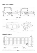
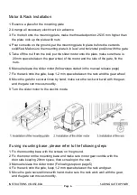
1. Reserve a place for the mounting plate 

2. Arrange all necessary electric wire in advance 

3. Fix the bolt onto the mounting plate, make the threaded portion 25-35 mm higher than  
    the plate, lock up the plate with nuts 

4. Pour cements on the ground, put the mounting plate in place before the cements   
    solidified. Make sure the mounting plate is in level and horizontal position with the gate. 

5. Take off the nut from the bolt, put the slider motor onto the plate, make sure there is   
     20mm space between the gear wheel of the motor and the side of the gate, fix the   
     nuts. 

6. Manual release the slider motor (follow steps stated in the manual release page) 

7. Fix the rack onto the gate, keep 1-2 mm space between the rack and the gear wheel 

8. Move the gate for several times by hand, make sure the rack work well with the gear,   
    and the gate can move smoothly. 

9. Turn the slider motor to the electric mode. 


If using mounting base, please refer to the following steps 

1. Fix the mounting base with the screws on the ground. 
2. Fix the motor on the mounting base and make sure motor gear contrite with the  
    door side keeping 20mm space, then screwing on the nuts. 
3. Manual release the slider motor (Following steps on page 5) 
4. Fix the rack onto the gate, keep 1-2 mm space between the rack and gear. 
5. Move the gate several times with hand, make sure the rack work well with the gear,      
    and the gate can move smoothly. 
 

Summary of Contents for VELOCE 80A

Page 1: ...INSTRUCTIONS VELOSE 80A Page 1 SLIDING GATE OPENER...

Page 2: ...cal Specifications 3 Mechanical Installation 4 Manual Release 5 Confirm Direction of Travel 6 Mounting the Sensor Magnets 7 Wiring 8 LED Diagram 9 Wiring For Optional Accessories 10 Remote Control Set...

Page 3: ...2 A5 B2 B5 6 Adjustment of force during fast speed slow speed A6 A7 B6 B7 7 Auto close function with adjustable closing time delay 8 Optional electric lock connection facility 9 Single or dual swing 1...

Page 4: ...800rpm Gate moving speed 13m min Gate Limit type Magnetic Limit Switch Operating Distance 50m Frequency 433 92 MHZ Remote Control Mode Close open Stop Pedestrain Open Auto Close Time 0 99 sec Adjustab...

Page 5: ...INSTRUCTIONS VELOSE 80A Page 5 SLIDING GATE OPENER Gear Rack Installation Mounting plate Base Dimension Installation Diagram...

Page 6: ...nuts 6 Manual release the slider motor follow steps stated in the manual release page 7 Fix the rack onto the gate keep 1 2 mm space between the rack and the gear wheel 8 Move the gate for several ti...

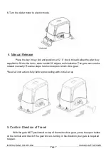
Page 7: ...the hole rotate handle 90 degree anti clockwise The gear can now be rotated manually Reverse steps to relock steps to relock drive gear Read all instructions fully before proceeding with initial set u...

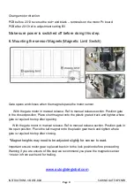
Page 8: ...ate in the closed position Place short magnet onto the plastic grated track and tighten where gate is required to stop after opening With the gate motor in manual release Ref to manual release section...

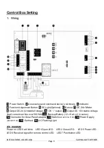
Page 9: ...r 8 Output DC 24 Unstable Voltage 9 OV output 10 Output DC 15V stable voltage load current can t be over 500 MA 11 Backup Battery 12 v 9 ah x 2 in series 12 Connector for Solar Panel adaptor 13 Switch...

Page 10: ...V OP CS SENSOR GND STOP CLOSE SENSOR GND Remarks Description Stable voltage output Open stop close Back up Concentration line Close Limit Open Limit Normally opening signal Concentration line Extensio...

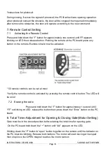
Page 11: ...should now be activated 50 remote controls can be set at most Verify the remote control is activated by pressing the remote control button The LED will be on of 7 2 Erasing the code Press and hold do...

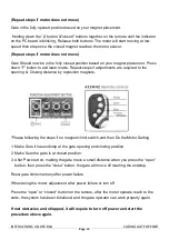
Page 12: ...the opening Closing distance by reposition magnets Please following the steps if no magnetic limit switch and then Do the Motor Setting 1 Make Sure it has endstop at the gate opening and closing posi...

Page 13: ...A0 Intermediate Stop Function with slow speed This refers to the sensitivity of gates when meeting obstacles during slow speed operation 0 99 20 Lower setting means the gates will be more sensitive to...

Page 14: ...control button for avoiding mis operation 0 2 0 If choose 0 normal operation If choose 1 delay 2 seconds then start the operation If choose 2 first press stop button for 2 seconds then close open but...

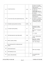
Page 15: ...the gate will automatically close 10 seconds after completing its opening C5 Pedestrian opening Distance setting 0 99 30 C6 Full speed opening setting 0 1 1 If choose 0 linear acceleration start soft...

Page 16: ...CB Debug and Error Code List Item Description E0 Low speed hampered stop E1 Fast speed hampered stop E2 Using limit switch stop E3 Normal operating without limit switch E4 Motor running over 2 minutes...

Reviews: