Pilot Operating Handbook
Cavalon
SECTION 7
SYSTEM DESCRIPTION
AutoGyro_POH_Cavalon 915iS
Revision 1.0 – Issue Date 08.MAY.2019
7-2
7.4
Fuel System
The fuel system consists of two tanks permanently
connected with a large bore crossover tube allowing
them to be considered as one large tank, with a single
filler port, fuel and ventilation lines, fuel level indicator,
tank water drain point and gascolator. The filler port is
located at the left hand side of the gyroplane. In order
to open the filler cap, lift, then turn the flap, and pull
out. Reverse to close cap. A lockable cap is available..
The tanks are installed behind the seats in their own
compartment and have a capacity of 100 litres. Fuel level can be checked visually using a
dip stick which has to be inserted diagonally from the fuel filler port (see 8.5).
The tanks are vented between the tanks in the mid channel, and via a single vent from the
tank filler neck to the outside below the aircraft. This is a 4mm bore pipe, so that in the
event of an accident little fuel is lost.
As an option, a low fuel level sensor may be installed in the left tank (required for UK and
USA Primary category). The LOW FUEL warning light is triggered as soon as 5 litres or less
of useable fuel remain in the tank.
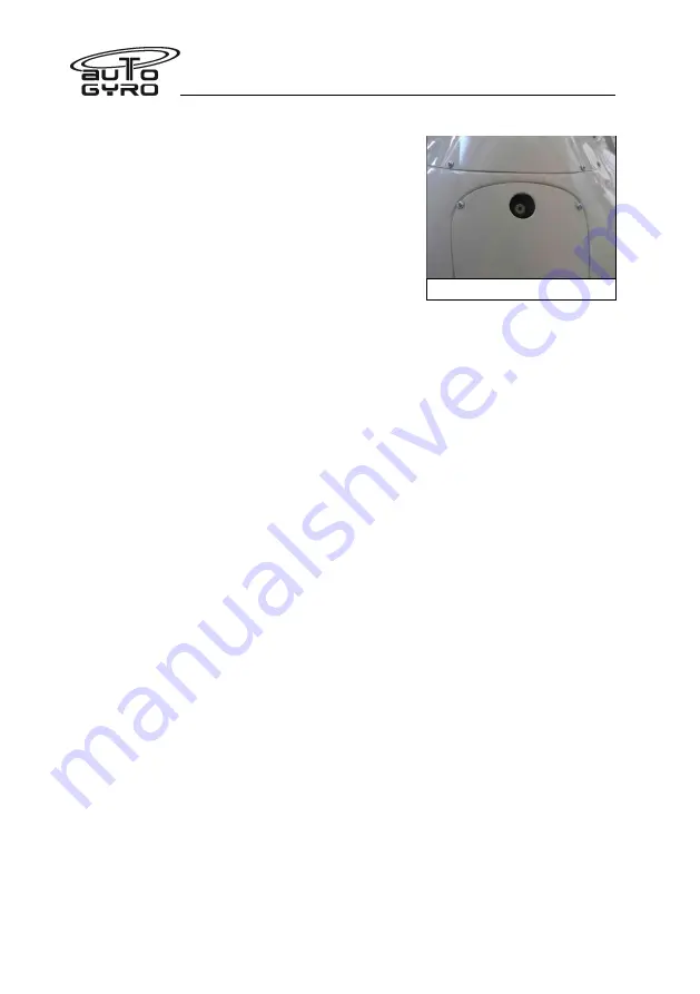
The gascolator drains through the body on the right side, near the suspension bow, allowing
easy access for drainage. Allows close properly after inspection!
The unit is accessible inside the engine cowls for access to the internal filter.
7.5
Pneumatic System
Aircraft trim, rotor brake and activation of the pre-rotator is controlled by a pneumatic
system, consisting of an electrically driven air compressor with filter/dryer, a pressure gauge
in the cockpit, solenoid valves, air lines, pneumatic actuators, and the respective cockpit
controls.
Trim function
Trimming is affected by varying trim pressure in the pneumatic trim actuator which is
installed in parallel with the rotor head tilt for pitch control. Aft or nose-up trimming activates
the electrical compressor and increases trim pressure, causing the actuator to retract, and
tilting the rotor disc aft. Forward trimming opens a pneumatic valve to reduce trim pressure
and allows the rotor disc to flatten, due to the spindle head offset and the gyroplane’s
weight. The actual trim condition is indicated on the trim/brake pressure gauge in the centre
panel of the cockpit.
Lateral/roll trim works accordingly, using a lateral pneumatic trim cylinder. Lateral trim
condition is indicated by a LED bar on the instrument panel.
Rotor brake
With the pneumatic mode selector in BRAKE position the operation of the pneumatic trim
actuator is reversed so that increased pressure causes the actuator to push the rotor head
up (or level) and presses a brake pad against the rotor head disc. In order to increase brake
Drain Valve


