Copyright of RotorSport UK Ltd
Document number RSUK0060
Page 74 of 101 Page issue 2, dated 12.09.11
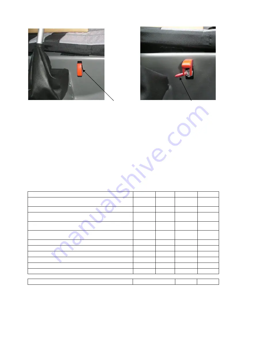
Fuel cock open, and protected by the red cover Cock closed, cover open
6.8 ELECTRICAL SYSTEM
The diagram attached in the Maintenance handbook shows the electrical system of the
autogyro.
With the Ignition switch OFF the engine is isolated. However, be aware that unless the
master switch is off other electrical items will work, and may draw current.
The starter should be used for short periods, 10secs maximum, as the nominal running
current draw from the starter motor may be up to 75amps. Overuse may result in internal
battery damage and early failure.
Use of optional items such as GPS units all draw a significant amount of current. The amount
will depend on individual circumstances.
Engine current availability and usage - Calidus gyroplane
Peak
Amperage
Peak
Wattage
Average
Amperage
Average
Wattage
Item
Engine and engine systems, inc one elect fuel pumps
(912ULS). Average assumes elect pump off
5A
60W
2A
24W
Engine and engine systems, inc two elect fuel pumps
(914UL). Average assumes one elect pump off
8A
96W
5A
60W
Funkwerk ATR 500 radio (2,8A when transmitting, 0.1A on
standby, 0.5A max.)
2.8A
39W
0.4A
5.6W
Funkwerk TRT800 Transponder at 13.8V
0.7A
10W
0.4A
5.5W
Garmin GPSmap max, normally about 4W
1A
12W
.33A
4W
Alternative LED Landing lights, 2x 2.5W (when on)
.4A
5W
Airworld strobe lights (average load is 1A)
2A
24W
1A
12W
Flymap (GPS) at max brightness
2.9A
35W
Actual current available from the alternator/rectifier
20A
250W


