Revised 11/19/99 • BACview
2
Hardware Guide
5
© 1999 Automated Logic Corporation
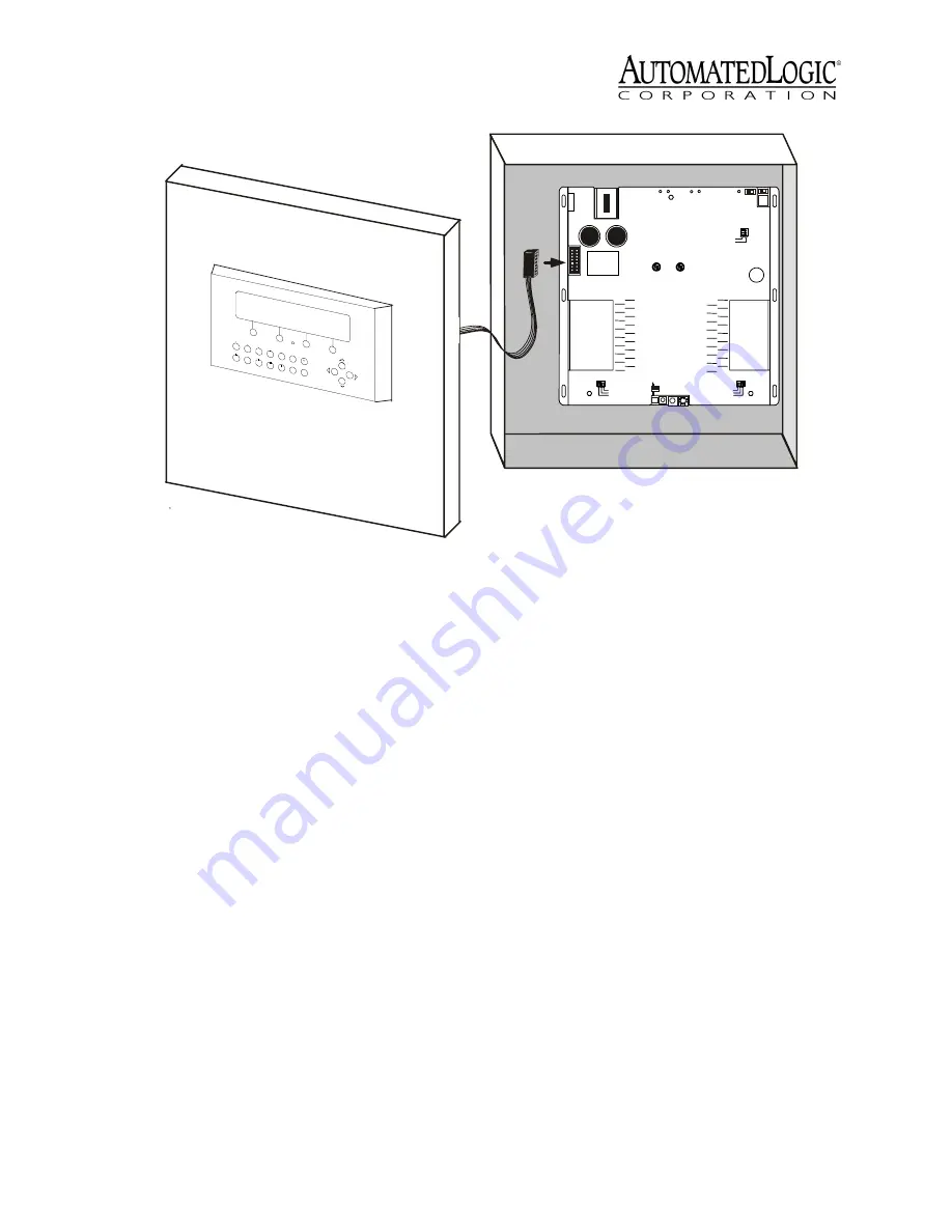
2. Plug the 14-pin TTL ribbon cable
connector into the Auxiliary Device port of
the module the BACview
2
will
communicate with.
3. Turn on the power to the module that the
BACview
2
will communicate with.
The BACview
2
is now properly wired. Before
the BACview
2
can be used, create, compile,
and transfer the screen file into the module.
Refer to the BACview
2
Programmer's Guide
and the
BACview Programmer’s Tutorial
for
more information.
Protection
The BACview
2
module is protected by an
internal Polyswitch on the incoming power.
This Polyswitch is not replaceable and will
reset itself if the condition that caused the
fault returns to normal.
Figure 4. Type II Mounting
Type: 0320
Cat. #
MODULE
I/ O
E x p a n s i o n
A - I n p u t S i g n a l
B - G n d / L o o p
P o w e r
I/ O
E x p a n s i o n
A
B
A
B
A
B
A
B
A
B
A
B
A
B
A
B
IN 1
IN 2
IN 3
IN 4
IN 5
IN 6
IN 7
IN 8
IN 9
IN 10
IN 11
IN 12
IN 13
IN 14
IN 15
IN 16
IN 2 4
IN 2 3
IN 2 2
IN 2 1
IN 2 0
IN 1 9
IN 1 8
IN 1 7
B
A
B
A
B
A
B
A
B
A
B
A
B
A
B
A
IN 32
IN 31
IN 30
IN 29
IN 28
IN 27
IN 26
IN 25
B
A
B
A
B
A
B
A
B
A
B
A
B
A
B
A
0-
2 0 m A0-
5 V d c
T h e r m i s t o r
/
d r y c o n -
t a c t
O n
O f f
G n d
2 4 V a c
C l a s s 2
2 4 V a c , 5 0 - 6 0
H z
3 5 V A , 1 . 5 A
U s e C o p p e r
C o n d u c t o r s O n l y
A
B
A
B
A
B
A
B
A
B
A
B
A
B
A
B
R u n
E r r o r
Control Module
P o w e r
A c c es s
P o r t
R x
N e t
+
N e t
-
O p t i o n a l
S h i e l d
F o r m a t
Tx
A u xi la r y
D e vi ce
P o r t
C M n e t
U n i v e r s a l In p u t
1 - 1 6
M o d e S e l e c t
0-
2 0 m A
0 - 5 V d c
T h e r m i s t o r /
d r y c o n t a c t
U n i v e r s a l I n p u t
1 7 - 3 2
M o d e S e l e c t
M o d u le
A d d r es s
0
5
1
4
2
3
9
6
8
7
1 0 's
1 's
A rc 1 5 6
R
L IST E D
8 8F O
O p e n En e r g y
M a na g e m e n t E q u i p m e n t
R
L IST E D
8 8F O
C
C M n e t M o d e
U s e S i n g l e C l a s s 2
S o u r c e O n l y
9 6 0 0 /3 8 .4 k


