background image


ZN551 Control Module 

Technical Instructions 


What is the ZN551 control module? ........................................................................... 2


Module driver and control program ................................................................2


Specifications ...............................................................................................2


Inputs ...........................................................................................................3


Room sensors................................................................................................3


Digital outputs...............................................................................................3


Analog outputs..............................................................................................3


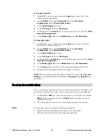
To mount the ZN551.................................................................................................. 4


Wiring for power ........................................................................................................ 4


To wire for power............................................................................................4


To address the ZN551................................................................................................ 5


Wiring for communications ........................................................................................ 5


Wiring specifications .....................................................................................5


To wire the ZN551 for communications ..........................................................5


Wiring inputs and outputs .......................................................................................... 6


Wiring specifications .....................................................................................6


To wire inputs and outputs .............................................................................7


Downloading memory ................................................................................................ 9


To download memory in WebCTRL ..................................................................9


To assign inputs or outputs to points........................................................................... 9


Input values.................................................................................................10


Output values ..............................................................................................10


Resolution values ........................................................................................11


Offset/Polarity values..................................................................................11


Using flow sensors................................................................................................... 12


To connect the duct tubes to the flow sensors ...............................................12


To wire the flow sensor to the control module................................................12


To set up the Airflow Control microblock.......................................................12


To set up the module driver ...................................................................................... 13


Driver ..........................................................................................................13


Device.........................................................................................................14


Notification Class #1 ...................................................................................14


Common Alarms..........................................................................................15


Custom Translation Tables...........................................................................15


To communicate through the local access port .......................................................... 16


To set up a Local Access connection in WebCTRL..........................................16


Troubleshooting ...................................................................................................... 16


Formatting the control module.....................................................................17


LED's..........................................................................................................17


Manufacture date........................................................................................18


Compliance ............................................................................................................ 18


Automated Logic Corporation • 1150 Roberts Blvd. • Kennesaw, GA 30144 • 770/429-3000 • Fax 770/429-3001 • 
www.automatedlogic.com • © 2005 Automated Logic Corporation. All rights reserved throughout the world. Automated 
Logic Corporation, the Automated Logic logo, WebCTRL, EIKON, BACview, SuperVision, and InterOp are registered 
trademarks, and Alert is a trademark of Automated Logic Corporation. BACnet

®

 is a registered trademark of ASHRAE. 

All other brand and product names are trademarked by their respective companies.  


Summary of Contents for ZN551

Page 1: ...re the flow sensor to the control module 12 To set up the Airflow Control microblock 12 To set up the module driver 13 Driver 13 Device 14 Notification Class 1 14 Common Alarms 15 Custom Translation Tables 15 To communicate through the local access port 16 To set up a Local Access connection in WebCTRL 16 Troubleshooting 16 Formatting the control module 17 LED s 17 Manufacture date 18 Compliance 1...

Page 2: ...d 2 are also configurable for 0 5 Vdc Inputs 4 and 5 are used when a LogiStat sensor is connected but are available if an RS room sensor is connected Input resolution 10 bit A D Digital outputs 5 digital outputs relay contacts rated at 1 A max 24 Vac Vdc Configured normally open Analog output 1 analog output 0 10 Vdc 5 mA max Output resolution 8 bit D A Memory 512 kB non volatile battery backed RA...

Page 3: ...t when the contacts are closed IN 1 IN 2 0 5 Vdc The output impedance of a 0 5 Vdc source must not exceed 100 Ohms The input impedance of the ZN551 is approximately 30 kOhm IN 4 IN 5 LogiStat IN 4 See Thermistor IN 5 Setpoint adjust Input voltages should be from 1 4 3 4 Vdc NOTE A LogiStat sensor connected to the ZN551 uses IN 4 and IN 5 An RS room sensor connected to the Rnet port does not use th...

Page 4: ...e same transformer that powers the ZN551 NOTE You can power several control modules from the same transformer if you maintain the same polarity To wire for power 1 Remove power from the 24 Vac transformer 2 Pull the screw terminal connector from the control module s power terminals labeled Gnd and 24 Vac 3 Connect the transformer wires to the screw terminal connector 4 Apply power to the transform...

Page 5: ...P communicating at 9600 bps 19 2 kbps 38 4 kbps or 76 8 kbps NOTE ARC156 is a unique implementation of the industry standard ARCNET For a summary of differences between ARCNET and ARC156 see the ARC156 Wiring Technical Instructions http info automatedlogic com For Use Maximum Length ARC156 22 AWG low capacitance twisted stranded shielded copper wire 2000 feet 610 meters MS TP A dedicated 22 AWG to...

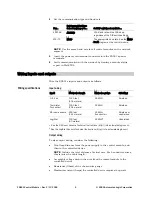
Page 6: ...et 305 meters 26 AWG Shielded Thermistor Dry contact 1000 feet 305 meters 22 AWG Shielded RS room sensors 500 feet 152 meters 22 AWG 4 conductor1 Shielded or unshielded LogiStat 100 feet 30 meters 22 AWG2 Unshielded 1 See the RS Room Sensors Technical Instructions http info automatedlogic com 2 See the LogiStat Sensors Technical Instructions http info automatedlogic com Output wiring To size outpu...

Page 7: ...ort to the terminal of the same name on the RS room sensor NOTE If wiring an RS room sensor with shielded wire connect the shield wire to the GND terminal with the ground wire For a LogiStat room sensor use the following table Wire this terminal on the LStat port To this terminal on the LogiStat sensor Gnd IN 4 IN 5 LED Gnd Temp SW LS5v 5 Set the appropriate jumpers on the ZN551 To use For IN 1 or...

Page 8: ... V Motor Valve Any AO Gnd Any AO NOTE Current from the analog outputs can drive a 20 mA device To use an analog output for this purpose you may need to add a 1 2 watt resistor in series with the device to achieve the required total resistance of 500 Ohms For example to drive a device that has 100 Ohms of resistance wire a 400 Ohm resistor in series with the 20 mA device to achieve 500 Ohms resista...

Page 9: ...local copy of the system database to the ZN551 s local access port See steps 1 3 of To communicate through the local access port page 16 To download memory in WebCTRL 1 On WebCTRL s CFG tree click Download 2 Select the Memory checkbox NOTE A memory download includes a Parameters and Schedules download 3 On the Network tree on the right select the control module you want to download to 4 Click Add ...

Page 10: ...e Engineering values associated with 0 Vdc Min and 5 Vdc Max 1 Thermistor Thermistor Select your Thermistor type or set up and select a Non Linear Custom Table2 N A Digital Binary BBI Dry Contact Dry Contact N A N A Input values 1 The sensor reads a value and sends a corresponding signal Volt mA or psi to the ZN551 s physical input The Analog Input microblock uses the Min and Max values to linearl...

Page 11: ...ol program uses 13 7 for any calculations downstream from the microblock Analog Output BAO The driver truncates the wire input value to the microblock before performing any scaling calculations EXAMPLE If the wire input value is 13 789 and you set the Resolution to 0 1 the microblock uses 13 7 for any scaling calculations Digital Inputs and Outputs N A Offset Polarity values Offset Polarity is not...

Page 12: ...with each actuator connected to two digital outputs To connect the duct tubes to the flow sensors USF 1 Connect the duct s total pressure tube to the USF s High connector 2 Connect the duct s static pressure tube to the USF s Low connector UDF Follow the procedure for a USF but connect one duct s tubes to the UDF s Flow 1 connectors and the other duct s tubes to the UDF s Flow 2 connectors To wire...

Page 13: ...he left of Flow Input AI Configuration 6 In the Sensor Type field under Calibration select No Translation 7 On the Logic page select the airflow control microblock for Flow 2 8 Repeat steps 2 through 6 for Flow 2 typing 2 in step 3 NOTE When performing test and balance follow the steps under Test and Balance on the Airflow Control microblock s Properties page Details tab in WebCTRL To set up the m...

Page 14: ...rent network is an MS TP network Notification Class 1 WebCTRL alarms use Notification Class 1 A BACnet alarm s Notification Class defines Alarm priority for Alarm Fault and Return to Normal states Options for BACnet alarm acknowledgement Where alarms should be sent recipients NOTE You may need to set up additional Notification Classes if your system will handle Life Safety alarms or if you need to...

Page 15: ...ier other than 1 WebCTRL processes alarms for any 32 bit Process Identifier Issue Confirmed Notifications Select to have a device continue sending an alarm message until it receives delivery confirmation from the recipient Common Alarms On these pages you can change the following control module alarm properties BACnet alarm object properties Enable disable Delays NOTE To set up alarm actions for c...

Page 16: ... 4 Relay switch to Network To set up a Local Access connection in WebCTRL 1 On the CFG tree select Connections 2 On the Configure tab click Add 3 From the Type drop down list select BACnet Local Access 4 Optional Edit the Description 5 Type the computer s Port number where your APT is connected 6 Set the Baud rate to 115200 7 Click Accept 8 On the View tab click the drop down arrow next to your de...

Page 17: ...network segment Tx The ZN551 is transmitting data over the network segment DO The digital output is active The Run and Error LED s indicate control module and network status If Run LED shows And Error LED shows Status is 2 flashes per second Off Normal 2 flashes per second 2 flashes alternating with Run LED Five minute auto restart delay after system error 2 flashes per second 3 flashes then off C...

Page 18: ...ear month and day of manufacture The month digit is in hexadecimal format Compliance This equipment has been tested and found to comply with the limits for a Class A digital device pursuant to Part 15 of the FCC Rules These limits are designed to provide reasonable protection against harmful interference when the equipment is operated in a commercial environment This equipment generates uses and c...

Reviews: