background image

Kicker

Aufbauanleitung 

zu Art.Nr. 2507200 ff.,  3649103 ff.

6


Als nachstes werden die Kickergriffe (P7) mit Hilfe der 

Schrauben (H8) und die Stangenendkappen befestigt.  


Achtung: achten Sie auf die richtige Anordnung der Figuren 

(siehe Grafik).


Der Torwart wird links und rechts mit jeweils einem Stellring 

(weiße Ringe) montiert. Die Stellringe halten den Torwart in 

der Position innerhalb des Torraums und verhindern ein zu 

weites verschieben nach rechts oder links. 


Justieren Sie dann die Balleinwurfschale (P5A) mit dem dazu-

gehörigen Gegenstück (P5B) und verwenden Sie hierfür die 

Schraube (H7). 


Abschließend müssen die Torzahlwerke (P6), wie in der 

Abbildung gezeigt, angebracht werden.


Next, the Kicker handles (P7) are fixed up with the screws 

(P8) and the pin up sleeve.  


Attention: pay attention to the correct order of the figures 

(see graphic).


Goalkeeper is mounted left and right with small white collets. 

The collets take the goalkeeper in postion near the goal area 

and prevent moving to far to left and right.  


Adjust the all insertion tray (P5A) with the counterpart (P5B) 

while using the screw (H7).


Finally attach the counter (P6) on top of the corpus as 

showed in the illustration.  

D

Abb./Fig. 5

5.) 

Achtung!

 Justieren Sie den FuBballkicker in der hochge-

klappten Position, indem Sie die Sicherungsstifte verwenden.

5.) 

ATTENTION! 

Adjust the Kicker in the „Fold Up“ postion while 

using the safety pins. 

Diesen Stellring nur an die Torwart- 

Stange montieren (2x)

This part only belongs on the goalie 

posts (twice)

Summary of Contents for 2507200

Page 1: ...ccer Table Comfort Automaten Hoffmann Tischkicker Comfort Aufbauanleitung Assembly manual Art 2507200 ff 3649103 ff 0221213 2021 Sportime Sportime c o Sport Thieme GmbH Helmstedter Straße 40 38368 Grasleben Germany www sportime de ...

Page 2: ...ver meiden Bitte lesen Sie die Aufbauanleitung sorgfältig um Verletzungen oder Beschädigungen zu ver meiden Folgende Werkzeuge werden zur Montage benötigt Schlitzschraubenzieher Kreuzschlitzschrauben zieher Akkuschrauber oder Hammer Werkzeug für Spannstift Innensechkant Schlüssel Please keep your instructions Your Model number is needed when you contact us Please read through this instruction book...

Page 3: ...ift Iron Pin 2x Querstrebe 1 Leg Support Bar A 1x Querstrebe 1 Leg Support Bar B 1x Querstrebe 2 Leg Support Bar A 1x Querstrebe 2 Leg Support Bar B 1x Korpus Main Frame 1x Gerades Bein A Leg A 1x Gerades Bein B Leg B 1x Gewinkeltes Bein A Leg A 1x Gewinkeltes Bein B Leg B 1x Verbindungsbrett Leg Panel 1x Balleinwurfschale A Ball entry cup A 2x Balleinwurfschale B Ball entry cup B 2x Torzählwerk S...

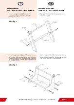
Page 4: ...iese mit den Schrauben H1 und den Unter legscheiben H2 Montieren Sie das Verbindungsbrett P4 mit den gewinkelten Beinen P3A und P3B und verwenden Sie hierfür die Unterlegscheiben H4 und die Schrauben H3 Abb Fig 2 Assembly instructions Important Note Use 2 adults to assemble the soccer table 1 Place the cross brace H11A between the straight legs P2A P2B Insert the cross brace H12A with screws H1 an...

Page 5: ...cherungsstifte H1O wie unten gezeigt ein 3 Adjust the legs P2A P2B P3A P3B at the corpus P1 with the help of the threaded rod H9 the washer H6 and the locking screw H5 Afterwards insert the locking pin H10 to fix up the legs as showed in the illustration 4 Schieben Sie nun die Kickerstangen C1 C2 und C3 so durch die Lager hindurch ein wie in der Abbildung gezeigt und montieren Sie die Kickerfigure...

Page 6: ...ildung gezeigt angebracht werden Next the Kicker handles P7 are fixed up with the screws P8 and the pin up sleeve Attention pay attention to the correct order of the figures see graphic Goalkeeper is mounted left and right with small white collets The collets take the goalkeeper in postion near the goal area and prevent moving to far to left and right Adjust the all insertion tray P5A with the cou...

Page 7: ...Kicker Aufbauanleitung zu Art Nr 2507200 ff 3649103 ff 7 D Demontage des Spielfeldes Step of disassemble the playfield Abb Fig 1 Abb Fig 2 ...

Page 8: ...Kicker Aufbauanleitung zu Art Nr 2507200 ff 3649103 ff 8 D Demontage des Spielfeldes Forts Step of disassemble the playfield Contin Abb Fig 3 Abb Fig 4 ...

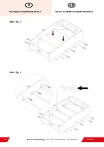
Page 9: ...Kicker Aufbauanleitung zu Art Nr 2507200 ff 3649103 ff 9 D Montage des Spielfeldes Step of assemble the playfield Abb Fig 1 Abb Fig 2 ...

Page 10: ...Kicker Aufbauanleitung zu Art Nr 2507200 ff 3649103 ff 10 D Montage des Spielfeldes Forts Step of assemble the playfield Contin Abb Fig 3 Abb Fig 4 ...

Page 11: ...her is no jarring allowed at any point during a game This is not the same as when a player on the opposite team moves his or her foos ball rods back and forth in an attempt to play defense The key this rule when a player hits the wall of the table with enough force to jar the ball or distract the opponent That is why this is a subjective rule that may be called more strict by certain fossball play...

Reviews: